Eaton : DILM32-XTED11-1(RA24)
105210 DILM32-XTED11-1(RA24)
DILM32-XTED11-1(RA24) /105210
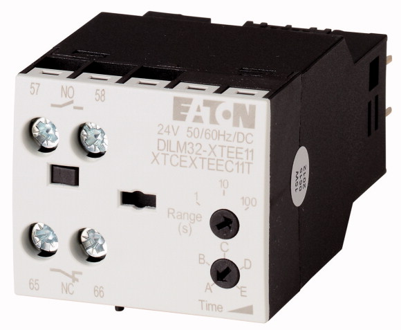
Zamanlayıcı modülü, 24VAC/DC, 0,05-1s, gecikmeli Zamanlayıcı modülü, Düşmede gecikmeli, yardımcı gerilimsiz, Üstten montajlı yardımcı kontaklarla birleştirilemez, Dahil. baskılayıcı devreler, Ürün yelpazesi: Aksesuarlar, Zaman aralığı: 0,05 - 1 s, Montaj konumu: Gerektiğinde, asılı hariç, Koruma Derecesi: IP20, Ağırlık: 0,08 kg, Şunlarla kullanım için: DILM7 - DILM38, DILMP20, DILMP32-DILMP45, DILA, DILMF7, DILMF11, DILMF14, DILMF25, DILMF32, Standartlar DIN EN 61812, IEC/EN 60947, VDE 0660, UL, CSA
Zamanlayıcı modülü, 24VAC/DC, 0,05-1s, gecikmeli
Zamanlayıcı modülü, Düşmede gecikmeli, yardımcı gerilimsiz, Üstten montajlı yardımcı kontaklarla birleştirilemez, Dahil. baskılayıcı devreler, Ürün yelpazesi: Aksesuarlar, Zaman aralığı: 0,05 - 1 s, Montaj konumu: Gerektiğinde, asılı hariç, Koruma Derecesi: IP20, Ağırlık: 0,08 kg, Şunlarla kullanım için: DILM7 - DILM38, DILMP20, DILMP32-DILMP45, DILA, DILMF7, DILMF11, DILMF14, DILMF25, DILMF32, Standartlar DIN EN 61812, IEC/EN 60947, VDE 0660, UL, CSA
| Product range | Accessories |
| Accessories | Timer modules |
| Description | Off-delayed, auxiliary voltage-free Cannot be combined with top mounting auxiliary contacts Incl. suppressor circuits |
| US | 24 V AC/DC |
| Time range | 0.05 - 1 s |
| For use with | DILM7 - DILM38 DILMP20 DILMP32-DILMP45 DILA DILMF7 DILMF11 DILMF14 DILMF25 DILMF32 |
| Contact sequence | |
| Standards | |
| Lifespan, mechanical >AC operated [Operations] |
DIN EN 61812, IEC/EN 60947, VDE 0660, UL, CSA |
| Lifespan, mechanical >DC operated [Operations] |
3 x 10⁶ |
| Climatic proofing | 3 x 10⁶ |
| Ambient temperature >Open |
Damp heat, constant, to IEC 60068-2-78 Damp heat, cyclic, to IEC 60068-2-30 |
| Ambient temperature >Enclosed |
-25 - +60 °C |
| Ambient temperature >Storage |
- 25 - 40 °C |
| Mounting position | - 40 - 80 °C |
| Mechanical shock resistance (IEC/EN 60068-2-27) >Half-sinusoidal shock, 10 ms >N/O contact |
As required, except suspended |
| Mechanical shock resistance (IEC/EN 60068-2-27) >Half-sinusoidal shock, 10 ms >N/C contact |
6 g |
| Degree of Protection | 6 g |
| Protection against direct contact when actuated from front (EN 50274) | IP20 |
| Weight | Finger and back-of-hand proof |
| Terminal capacities >Solid |
0.08 kg |
| Terminal capacities >Flexible with ferrule |
1 x (0.75 - 2.5) 2 x (0.75 - 1.5) mm2 |
| Terminal capacities >Solid or stranded |
1 x (0.75 - 1.5) 2 x (0.75 - 1.5) mm2 |
| Terminal screw | 18 - 14 AWG |
| Pozidriv screwdriver | M3.5 |
| Standard screwdriver | 2 Size |
| Max. tightening torque | 0.8 x 5.5 1 x 6 mm |
| Rated impulse withstand voltage [Uimp] | 1.2 Nm |
| Overvoltage category/pollution degree | |
| Rated insulation voltage [Ui] | 4000 V AC |
| Rated operational voltage [Ue ] | III/3 |
| Rated operational current [Ie
] >AC-15 >220 V 230 V 240 V [Ie] |
250 V AC |
| Rated operational current [Ie
] >DC-13 >DC-13 L/R - 15 ms >Contacts in series: >1 [24 V] |
250 V |
| Rated operational current [Ie
] >DC-13 >DC-13 L/R - 15 ms >Contacts in series: >1 [60 V] |
3 A |
| Rated operational current [Ie
] >DC-13 >DC-13 L/R - 15 ms >Contacts in series: >1 [110 V] |
1 A |
| Rated operational current [Ie
] >DC-13 >DC-13 L/R - 15 ms >Contacts in series: >1 [220 V] |
0.2 A |
| Rated operational current [Ie
] >DC-13 >DC L/R ≦ 50 ms >Contacts in series: >1 [24 V] |
0.2 A |
| Rated operational current [Ie
] >DC-13 >DC L/R ≦ 50 ms >Contacts in series: >1 [60 V] |
0.1 A |
| Rated operational current [Ie
] >DC-13 >DC L/R ≦ 50 ms >Contacts in series: >1 [110 V] |
1 A |
| Rated operational current [Ie
] >DC-13 >DC L/R ≦ 50 ms >Contacts in series: >1 [220 V] |
0.2 A |
| Rated operational current [Ie
] >DC-13 >DC-13 L/R - 300 ms >Contacts in series: >1 [24 V] |
0.2 A |
| Rated operational current [Ie
] >DC-13 >DC-13 L/R - 300 ms >Contacts in series: >1 [60 V] |
0.1 A |
| Rated operational current [Ie
] >DC-13 >DC-13 L/R - 300 ms >Contacts in series: >1 [110 V] |
1 A |
| Rated operational current [Ie
] >DC-13 >DC-13 L/R - 300 ms >Contacts in series: >1 [220 V] |
0.2 A |
| Safe isolation to EN 61140 >between coil and auxiliary contacts |
0.2 A |
| Safe isolation to EN 61140 >between the auxiliary contacts |
0.1 A |
| Conventional thermal current [Ith ] | 250 V AC |
| Short-circuit rating without welding >max. fuse |
250 V AC |
| Voltage tolerance >Pick-up voltage >AC operated [Pick-up] 0.85 - 1.1 x Uc
Voltage tolerance >Pick-up voltage >DC operated [Pick-up] [Pick-up] 0.7 - 1.2 x Uc
Power consumption >60 °C [Sealing] |
4 A |
| Power consumption >AC operated [Sealing] |
4 A gG/gL |
| duty factor | |
| Maximum operating frequency >Max. operating frequency |
0.85 - 1.1 x Uc |
| Maximum operating frequency >Can be combined with auxiliary contact |
0.7 - 1.2 x Uc |
| Conventional thermal current Ith = Ie AC-1 >On-delayed |
2 VA |
| Conventional thermal current Ith = Ie AC-1 >Off-delayed |
1.8 W |
| AC operated 50 Hz [Deviation] | 100 % DF |
| Recovery time (after 100% time delay) | 3600 Ops/h |
| contact changeover time >DILM32-XTEE11/DILM32-XTED11 [tu] |
360 Ops./h |
| contact changeover time >DILM32-XTEY20 [tu] |
< 50 ms |
| Notes | < 200 ms |
| Auxiliary contacts >Pilot Duty >AC operated |
< 5 % |
| Auxiliary contacts >Pilot Duty >DC operated |
70 ms |
| Auxiliary contacts >General Use >AC |
10 ms |
| Auxiliary contacts >General Use >AC |
50 ms |
| Auxiliary contacts >General Use >DC |
|
| Auxiliary contacts >General Use >DC |
For rated operational current: Making and breaking conditions to DC-13, L/R constant as stated Max. fuses for short-circuit protection: Transparent overlay ″Fuses″ for time/current characteristics (please enquire) For pick-up voltage, DC operated:Pure DC, AC bridge rectifier or smoothed double-wave rectification. |
| Short Circuit Current Rating >Basic Rating >SCCR |
|
| Short Circuit Current Rating >Basic Rating >max. Fuse |
B300 |
| Short Circuit Current Rating >Basic Rating >max. CB |
R300 |
| Short Circuit Current Rating >480 V High Fault >SCCR (fuse) |
240 V |
| Short Circuit Current Rating >480 V High Fault >max. Fuse |
5 A |
| Short Circuit Current Rating >480 V High Fault >SCCR (CB) |
24 V |
| Short Circuit Current Rating >480 V High Fault >max. CB |
5 A |
| Short Circuit Current Rating >600 V High Fault >SCCR (fuse) |
5 kA |
| Short Circuit Current Rating >600 V High Fault >max. Fuse |
125 A |
| Short Circuit Current Rating >600 V High Fault >SCCR (CB) |
125 A |
| Short Circuit Current Rating >600 V High Fault >max. CB |
10/100 kA |
| Rated operational current for specified heat dissipation [In] | 125/70 Class J A |
| Heat dissipation per pole, current-dependent [Pvid] | 10/65 kA |
| Equipment heat dissipation, current-dependent [Pvid] | 50/32 A |
| Static heat dissipation, non-current-dependent [Pvs] | 10/100 kA |
| Heat dissipation capacity [Pdiss] | 125/125 Class J A |
| Operating ambient temperature min. | 10/22 kA |
| Operating ambient temperature max. | 50/32 A |
| 10.2 Strength of materials and parts >10.2.2 Corrosion resistance |
|
| 10.2 Strength of materials and parts >10.2.3.1 Verification of thermal stability of enclosures |
0 A |
| 10.2 Strength of materials and parts >10.2.3.2 Verification of resistance of insulating materials to normal heat |
0 W |
| 10.2 Strength of materials and parts >10.2.3.3 Verification of resistance of insulating materials to abnormal heat and fire due to internal electric effects |
0 W |
| 10.2 Strength of materials and parts >10.2.4 Resistance to ultra-violet (UV) radiation |
1.8 W |
| 10.2 Strength of materials and parts >10.2.5 Lifting |
0 W |
| 10.2 Strength of materials and parts >10.2.6 Mechanical impact |
-25 °C |
| 10.2 Strength of materials and parts >10.2.7 Inscriptions |
+60 °C |
| 10.3 Degree of protection of ASSEMBLIES | |
| 10.4 Clearances and creepage distances | Meets the product standard´s requirements. |
| 10.5 Protection against electric shock | Meets the product standard´s requirements. |
| 10.6 Incorporation of switching devices and components | Meets the product standard´s requirements. |
| 10.7 Internal electrical circuits and connections | Meets the product standard´s requirements. |
| 10.8 Connections for external conductors | Meets the product standard´s requirements. |
| 10.9 Insulation properties >10.9.2 Power-frequency electric strength |
Does not apply, since the entire switchgear needs to be evaluated. |
| 10.9 Insulation properties >10.9.3 Impulse withstand voltage |
Does not apply, since the entire switchgear needs to be evaluated. |
| 10.9 Insulation properties >10.9.4 Testing of enclosures made of insulating material |
Meets the product standard´s requirements. |
| 10.10 Temperature rise | Does not apply, since the entire switchgear needs to be evaluated. |
| 10.11 Short-circuit rating | Meets the product standard´s requirements. |
| 10.12 Electromagnetic compatibility | Does not apply, since the entire switchgear needs to be evaluated. |
| 10.13 Mechanical function | Does not apply, since the entire switchgear needs to be evaluated. |
| Switching function | Is the panel builder´s responsibility. |
| Setting time | Is the panel builder´s responsibility. |
| Number of contacts as normally open contact | Is the panel builder´s responsibility. |
| Number of contacts as normally closed contact | Is the panel builder´s responsibility. |
| Number of contacts as change-over contact | Is the panel builder´s responsibility. |
| Operating principle | The panel builder is responsible for the temperature rise calculation. Eaton will provide heat dissipation data for the devices. |
| Product Standards | Is the panel builder´s responsibility. The specifications for the switchgear must be observed. |
| UL File No. | Is the panel builder´s responsibility. The specifications for the switchgear must be observed. |
| UL Category Control No. | The device meets the requirements, provided the information in the instruction leaflet (IL) is observed. |
| CSA File No. | |
| CSA Class No. | |
| North America Certification | Time-delay dropped out |
Tüm ürünlerimiz, zorlu çalışma koşullarında dahi maksimum güvenilirlik sunar ve işletmenizin operasyonlarını sorunsuz şekilde sürdürmesine yardımcı olur. Endüstriyel otomasyon, enerji yönetimi, kablolama çözümleri ve daha birçok alanda sunduğumuz ürünler, farklı sektörlerdeki ihtiyaçlara esneklikle uyum sağlar.
Ayrıca, ürünlerimiz sadece kaliteli malzemelerle üretilmiş olup, uluslararası standartlara uygunluk göstermektedir. Müşterilerimize sunduğumuz çözümlerle, operasyonel verimliliklerini artırmalarına ve maliyetlerini optimize etmelerine olanak tanıyoruz. Teknolojik gelişmeleri yakından takip eden firmamız, sürekli olarak yenilikçi ürünler sunarak, müşterilerimizin rekabet avantajı elde etmesine destek vermektedir.
Her bir ürün sayfamızda, teknik detaylar, kullanım alanları ve ürün özelliklerine dair kapsamlı bilgilere ulaşabilirsiniz. Endüstriyel süreçlerinizi güçlendirmek için ihtiyacınız olan tüm ürünleri sitemizden keşfedebilir, sorunsuz bir satın alma deneyimi yaşayabilirsiniz.
Benzer Ürünler


Aradığınız ürünü bulamıyor musunuz?
SİZE YARDIMCI OLALIM
Aradığınız Ürünü Bulamadınız mı? Bize Bildirin, Sizin İçin Tedarik Edelim!
Web sitemizde yer almayan ya da stokta bulunmayan ürünleri mi arıyorsunuz? İhtiyacınızı bize bildirin, uzman ekibimiz en kısa sürede sizinle iletişime geçerek size en uygun çözümü bulsun.