Eaton : LS-S02-120AFT-ZBZ/X
106778 LS-S02-120AFT-ZBZ/X
LS-S02-120AFT-ZBZ/X /106778
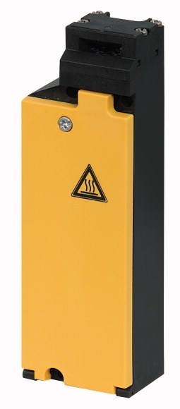
Pozisyon anahtarı, 2 N/K, temel, yay kuvveti Konum anahtarı, Temel fonksiyon: Konum anahtarları, Güvenlik konum anahtarları, Parça grubu referansı: LS…ZBZ/X, Ürün yelpazesi: Yaylı kilitlemeli temel üniteler (kapalı devre prensibi), Koruma Derecesi: IP65, Özellikler: Temel cihaz , genişletilebilir, Ortam sıcaklığı: -25 - +40 °C, Açıklama: Kilit izlemeli, yardımcı serbest bırakma mekanizmalı, Kapı konumunun izlenmesi: sürekli, Kontaklar N/C = Normalde kapalı: 2 NC, Notlar: = güvenlik fonksiyonu, IEC/EN 60947-5-1'e göre pozitif açıklık, Manyetik sürücü için nominal kontrol gerilimi: Us= 120 V 50/60 Hz V, Gövde: Yalıtımlı malzeme, Bağlantı tipi: Vidalı terminal, Standartlar: IEC/EN 60947
Pozisyon anahtarı, 2 N/K, temel, yay kuvveti
Konum anahtarı, Temel fonksiyon: Konum anahtarları, Güvenlik konum anahtarları, Parça grubu referansı: LS…ZBZ/X, Ürün yelpazesi: Yaylı kilitlemeli temel üniteler (kapalı devre prensibi), Koruma Derecesi: IP65, Özellikler: Temel cihaz , genişletilebilir, Ortam sıcaklığı: -25 - +40 °C, Açıklama: Kilit izlemeli, yardımcı serbest bırakma mekanizmalı, Kapı konumunun izlenmesi: sürekli, Kontaklar N/C = Normalde kapalı: 2 NC, Notlar: = güvenlik fonksiyonu, IEC/EN 60947-5-1'e göre pozitif açıklık, Manyetik sürücü için nominal kontrol gerilimi: Us= 120 V 50/60 Hz V, Gövde: Yalıtımlı malzeme, Bağlantı tipi: Vidalı terminal, Standartlar: IEC/EN 60947
| Basic function | Position switches Safety position switches |
| Part group reference | LS…ZBZ/X |
| Product range | Basic units with spring-powered interlock (closed-circuit principle) |
| Degree of Protection | IP65 |
| Features | Basic device, expandable |
| Ambient temperature | -25 - +40 °C |
| Description | With interlock monitoring with auxiliary release mechanism Monitoring of door position: continuous |
| Approval | |
| N/C = Normally closed | 2 NC  |
| Notes | = safety function, by positive opening to IEC/EN 60947-5-1 |
| Contact sequence | |
| Rated control voltage for magnetic drive [Us ] | 120 V 50/60 Hz V |
| Housing | Insulated material |
| Connection type | Screw terminal |
| Notes | Switch must never be used as a mechanical stop! The operating head can be rotated manually in 90° steps without tools to suit the specified level of actuation. With the actuator inserted, the N/O contact is open and the N/C contact is closed. For degree of protection IP65, use V-M20 (206910) cable glands with connecting thread of max. 9 mm length. In the event of power failure (e.g., during commissioning), the device can be released with a screwdriver. The auxiliary release mechanism must be sealed! → Instructional leaflet IL 05208005Z |
| Standards | IEC/EN 60947 |
| Climatic proofing | Damp heat, constant, to IEC 60068-2-78; damp heat, cyclical, to IEC 60068-2-30 |
| Ambient temperature | -25 - +40 °C |
| Mounting position | As required |
| Degree of Protection | IP65 |
| Terminal capacities >Solid |
1 x (0.75 - 2.5) 2 x (0.75 - 1.5) mm2 |
| Terminal capacities >Flexible with ferrule |
1 x (0.5 - 1.5) 2 x (0.5 - 1.5) mm2 |
| Terminal screw | PH1 |
| Tightening torque for terminal screw | 0.9 Nm |
| Repetition accuracy | 0.02 mm |
| Rated impulse withstand voltage [Uimp] | 4000 V AC |
| Rated insulation voltage [Ui ] | 400 V |
| Overvoltage category/pollution degree | III/3 |
| Rated operational current [Ie
] >AC-15 >24 V [Ie ] |
6 A |
| Rated operational current [Ie
] >AC-15 >220 V 230 V 240 V [Ie] |
6 A |
| Rated operational current [Ie
] >AC-15 >380 V 400 V 415 V [Ie] |
4 A |
| Rated operational current [Ie
] >DC-13 >24 V [Ie ] |
3 A |
| Rated operational current [Ie
] >DC-13 >110 V [Ie ] |
0.8 A |
| Rated operational current [Ie
] >DC-13 >220 V [Ie ] |
0.3 A |
| Supply frequency | max. 400 Hz |
| Short-circuit rating to IEC/EN 60947-5-1 >max. fuse |
6 A gG/gL |
| Rated conditional short-circuit current | 1 kA |
| Lifespan, mechanical [Operations] | 1 x 10⁶ |
| Mechanical shock resistance (half-sinusoidal shock, 20 ms) >Standard-action contact |
10 g |
| Operating frequency [Operations/h] | ≦ 800 |
| Mechanical >Actuating force at beginning/end of stroke |
25/15 (plug-in/pull-out) N |
| Mechanical >Mechanical holding force acc. to GS-ET-19 (04/2004) >XG, XW, XNG |
1700 N |
| Mechanical >Mechanical holding force acc. to GS-ET-19 (04/2004) >XWA, XFG, XF |
1600 N |
| Mechanical >Mechanical holding force acc. to GS-ET-19 (04/2004) >XNW |
1200 N |
| Electromechanical >For magnet >Power consumption >at 120 V AC |
8 VA |
| Electromechanical >For magnet >Power consumption >at 230 V AC |
11 VA |
| Electromechanical >For magnet >Power consumption >at 24 V DC |
8 W |
| Electromechanical >Pick-up and drop-out values |
0.85 - 1.1 x Us |
| Electromechanical >Magnet duty factor |
100 % ED |
| Rated operational current for specified heat dissipation [In] | 6 A |
| Heat dissipation per pole, current-dependent [Pvid] | 0.13 W |
| Equipment heat dissipation, current-dependent [Pvid] | 0 W |
| Static heat dissipation, non-current-dependent [Pvs] | 0 W |
| Heat dissipation capacity [Pdiss] | 0 W |
| Operating ambient temperature min. | -25 °C |
| Operating ambient temperature max. | +40 °C |
| 10.2 Strength of materials and parts >10.2.2 Corrosion resistance |
Meets the product standard´s requirements. |
| 10.2 Strength of materials and parts >10.2.3.1 Verification of thermal stability of enclosures |
Meets the product standard´s requirements. |
| 10.2 Strength of materials and parts >10.2.3.2 Verification of resistance of insulating materials to normal heat |
Meets the product standard´s requirements. |
| 10.2 Strength of materials and parts >10.2.3.3 Verification of resistance of insulating materials to abnormal heat and fire due to internal electric effects |
Meets the product standard´s requirements. |
| 10.2 Strength of materials and parts >10.2.4 Resistance to ultra-violet (UV) radiation |
Meets the product standard´s requirements. |
| 10.2 Strength of materials and parts >10.2.5 Lifting |
Does not apply, since the entire switchgear needs to be evaluated. |
| 10.2 Strength of materials and parts >10.2.6 Mechanical impact |
Does not apply, since the entire switchgear needs to be evaluated. |
| 10.2 Strength of materials and parts >10.2.7 Inscriptions |
Meets the product standard´s requirements. |
| 10.3 Degree of protection of ASSEMBLIES | Does not apply, since the entire switchgear needs to be evaluated. |
| 10.4 Clearances and creepage distances | Meets the product standard´s requirements. |
| 10.5 Protection against electric shock | Does not apply, since the entire switchgear needs to be evaluated. |
| 10.6 Incorporation of switching devices and components | Does not apply, since the entire switchgear needs to be evaluated. |
| 10.7 Internal electrical circuits and connections | Is the panel builder´s responsibility. |
| 10.8 Connections for external conductors | Is the panel builder´s responsibility. |
| 10.9 Insulation properties >10.9.2 Power-frequency electric strength |
Is the panel builder´s responsibility. |
| 10.9 Insulation properties >10.9.3 Impulse withstand voltage |
Is the panel builder´s responsibility. |
| 10.9 Insulation properties >10.9.4 Testing of enclosures made of insulating material |
Is the panel builder´s responsibility. |
| 10.10 Temperature rise | The panel builder is responsible for the temperature rise calculation. Eaton will provide heat dissipation data for the devices. |
| 10.11 Short-circuit rating | Is the panel builder´s responsibility. The specifications for the switchgear must be observed. |
| 10.12 Electromagnetic compatibility | Is the panel builder´s responsibility. The specifications for the switchgear must be observed. |
| 10.13 Mechanical function | The device meets the requirements, provided the information in the instruction leaflet (IL) is observed. |
| Width sensor | 60 mm |
| Diameter sensor | 0 mm |
| Height of sensor | 173 mm |
| Length of sensor | 39 mm |
| Rated operation current Ie at AC-15, 24 V | 6 A |
| Rated operation current Ie at AC-15, 125 V | 6 A |
| Rated operation current Ie at AC-15, 230 V | 6 A |
| Rated operation current Ie at DC-13, 24 V | 3 A |
| Rated operation current Ie at DC-13, 125 V | 0.8 A |
| Rated operation current Ie at DC-13, 230 V | 0.3 A |
| Switching function | Slow-action switch |
| Switching function latching | No |
| Output electronic | No |
| Forced opening | Yes |
| Number of safety auxiliary contacts | 2 |
| Number of contacts as normally closed contact | 2 |
| Number of contacts as normally open contact | 0 |
| Number of contacts as change-over contact | 0 |
| Type of interface | None |
| Type of interface for safety communication | None |
| Construction type housing | Cuboid |
| Material housing | Plastic |
| Coating housing | Other |
| Type of control element | Other |
| Alignment of the control element | Other |
| Type of electric connection | Other |
| With status indication | No |
| Suitable for safety functions | Yes |
| Explosion safety category for gas | None |
| Explosion safety category for dust | None |
| Ambient temperature during operating | 25 - 70 °C |
| Degree of protection (IP) | IP65 |
| Degree of protection (NEMA) | 13 |
| Product Standards | IEC/EN 60947-5; UL 508; CSA-C22.2 No. 14; CE marking |
| UL File No. | E29184 |
| UL Category Control No. | NKCR |
| CSA File No. | 12528 |
| CSA Class No. | 3211-03 |
| North America Certification | UL listed, CSA certified |
| Degree of Protection | IEC: IP65, UL/CSA Type 3R, 4X (indoor use only), 12, 13 |
Tüm ürünlerimiz, zorlu çalışma koşullarında dahi maksimum güvenilirlik sunar ve işletmenizin operasyonlarını sorunsuz şekilde sürdürmesine yardımcı olur. Endüstriyel otomasyon, enerji yönetimi, kablolama çözümleri ve daha birçok alanda sunduğumuz ürünler, farklı sektörlerdeki ihtiyaçlara esneklikle uyum sağlar.
Ayrıca, ürünlerimiz sadece kaliteli malzemelerle üretilmiş olup, uluslararası standartlara uygunluk göstermektedir. Müşterilerimize sunduğumuz çözümlerle, operasyonel verimliliklerini artırmalarına ve maliyetlerini optimize etmelerine olanak tanıyoruz. Teknolojik gelişmeleri yakından takip eden firmamız, sürekli olarak yenilikçi ürünler sunarak, müşterilerimizin rekabet avantajı elde etmesine destek vermektedir.
Her bir ürün sayfamızda, teknik detaylar, kullanım alanları ve ürün özelliklerine dair kapsamlı bilgilere ulaşabilirsiniz. Endüstriyel süreçlerinizi güçlendirmek için ihtiyacınız olan tüm ürünleri sitemizden keşfedebilir, sorunsuz bir satın alma deneyimi yaşayabilirsiniz.
Benzer Ürünler


Aradığınız ürünü bulamıyor musunuz?
SİZE YARDIMCI OLALIM
Aradığınız Ürünü Bulamadınız mı? Bize Bildirin, Sizin İçin Tedarik Edelim!
Web sitemizde yer almayan ya da stokta bulunmayan ürünleri mi arıyorsunuz? İhtiyacınızı bize bildirin, uzman ekibimiz en kısa sürede sizinle iletişime geçerek size en uygun çözümü bulsun.