Eaton : EU5E-SWD-4D2R
116383 EU5E-SWD-4D2R
EU5E-SWD-4D2R /116383
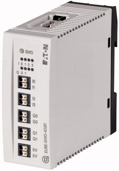
SWD I/O modülü, 24 V DC, 4 dijital giriş, 2 dijital röle çıkışı 3 A Dijital I/O sinyallerinin bağlantısı için SmartWire-DT abonesi, otomatik adres ayarı, 4 dijital girişli modül 24VDC, 2 dijital röle çıkışı 250VAC, 3 A, kelepçe tipi bastırmalı terminallerle bağlantı
SWD I/O modülü, 24 V DC, 4 dijital giriş, 2 dijital röle çıkışı 3 A
Dijital I/O sinyallerinin bağlantısı için SmartWire-DT abonesi, otomatik adres ayarı, 4 dijital girişli modül 24VDC, 2 dijital röle çıkışı 250VAC, 3 A, kelepçe tipi bastırmalı terminallerle bağlantı
| Product range | SmartWire-DT slave |
| Basic function | Digital modules |
| Function | For connection of digital I/O signals |
| Digital | 4 |
| Relay | 2 |
| Connection to SmartWire-DT | yes |
| Standards | IEC/EN 61131-2 |
| Approvals >Approvals |
UL CSA |
| Approvals >shipping classification |
DNV GL BV LRS |
| Approvals | |
| Dimensions (W x H x D) | 35 x 90 x 101 mm |
| Weight | 0.1 kg |
| Mounting | Top-hat rail IEC/EN 60715, 35 mm |
| Mounting position | As required |
| Power supply >Power loss [P] |
1 W |
| Climatic proofing | Dry heat to IEC 60068-2-2 Damp heat as per EN 60068-2-3 |
| Air pressure (operation) | 795 - 1080 hPa |
| Ambient temperature >Operation [ϑ] |
-25 - +55 °C |
| Ambient temperature >Storage / Transport [ϑ] |
-40 - +70 °C |
| Relative humidity >Condensation |
Take appropriate measures to prevent condensation |
| Relative humidity >Relative humidity, non-condensing (IEC/EN 60068-2-30) |
5 - 95 % |
| Protection type (IEC/EN 60529, EN50178, VBG 4) | IP20 |
| Vibrations (IEC/EN 61131-2:2008) >Constant amplitude 3,5 mm |
5 - 8.4 Hz |
| Vibrations (IEC/EN 61131-2:2008) >Constant acceleration 1 g |
8.4 - 150 Hz |
| Mechanical shock resistance (IEC/EN 60068-2-27) semi-sinusoidal 15 g/11 ms | 9 Impacts |
| Drop to IEC/EN 60068-2-31 [Drop height] | 50 mm |
| Free fall, packaged (IEC/EN 60068-2-32) | 0.3 m |
| Overvoltage category | II |
| Pollution degree | 2 |
| Electrostatic discharge (IEC/EN 61131-2:2008) >Air discharge (Level 3) |
8 kV |
| Electrostatic discharge (IEC/EN 61131-2:2008) >Contact discharge (Level 2) |
4 kV |
| Electromagnetic fields (IEC/EN 61131-2:2008) >80 - 1000 MHz |
10 V/m |
| Electromagnetic fields (IEC/EN 61131-2:2008) >1.4 - 2 GHz |
3 V/m |
| Electromagnetic fields (IEC/EN 61131-2:2008) >2 - 2.7 GHz |
1 V/m |
| Radio interference suppression (SmartWire-DT) | EN 55011 Class A |
| Burst (IEC/EN 61131-2:2008, Level 3) >Supply cable |
2 kV |
| Burst (IEC/EN 61131-2:2008, Level 3) >Signal lines |
1 kV |
| Burst (IEC/EN 61131-2:2008, Level 3) >SmartWire-DT cables |
1 kV |
| Surge (IEC/EN 61131-2:2008, Level 1) >Surge I/O cables |
1 kV |
| Radiated RFI (IEC/EN 61131-2:2008, Level 3) | 10 V |
| Station type | SmartWire-DT slave |
| Setting the baud rate | automatic |
| Baud rate (data transfer speed) | maximum250 kbps |
| Status SmartWire-DT | Green LED |
| Connection | Plug, 8-pole Connection plug: external device plug SWD4-8SF2-5 |
| Current consumption [Ie] | 45 mA |
| Terminal for I/O sensor >Connection type |
Push in terminals |
| Terminal for I/O sensor >Solid |
0.2 - 1.5 (AWG 24 - 16) mm2 |
| Terminal for I/O sensor >Flexible with ferrule |
0.25 - 1.5 (AWG 24 - 16) mm2 |
| Terminal for I/O sensor | Minimum length 8 mm |
| Quantity | 4 |
| Input current | Normally 4 at 24 V DC mA |
| Limit value type 1 | Low < 5V DC;High > 15V DC |
| Input delay | High->Low < 0.2 ms Low->High < 0.2 ms |
| Status display inputs | yellow LED |
| Number | 2 |
| Contact type art | N/O contact |
| Operations >Utilization category AC-1, 250 V, 4 A |
> 5 x 10⁴ |
| Operations >Utilization category AC-15, 250 V, 3 A |
> 5 x 10⁴ |
| Operations >Utilization category DC-13, 24 V, 1 A |
> 2 x 10⁵ |
| Safe isolation according to EN 50178 | 230 V AC |
| Minimum load current | 100 mA , 12 V DC mA |
| Pick-up/drop-out time | 5/2.5 ms |
| Bounce duration | Normally 1.5 ms |
| Short-circuit protection | external 4 A gL/gG |
| Status display for relay outputs | yellow LED |
| Inputs for SmartWire-DT | Yes |
| Outputs to SmartWire-DT | Yes |
| Output to output | Yes |
| Rated operational current for specified heat dissipation [In] | 0 A |
| Heat dissipation per pole, current-dependent [Pvid] | 0 W |
| Equipment heat dissipation, current-dependent [Pvid] | 0 W |
| Static heat dissipation, non-current-dependent [Pvs] | 1 W |
| Heat dissipation capacity [Pdiss] | 0 W |
| Operating ambient temperature min. | -25 °C |
| Operating ambient temperature max. | +55 °C |
| Degree of Protection | IP20 |
| 10.2 Strength of materials and parts >10.2.2 Corrosion resistance |
Meets the product standard´s requirements. |
| 10.2 Strength of materials and parts >10.2.3.1 Verification of thermal stability of enclosures |
Meets the product standard´s requirements. |
| 10.2 Strength of materials and parts >10.2.3.2 Verification of resistance of insulating materials to normal heat |
Meets the product standard´s requirements. |
| 10.2 Strength of materials and parts >10.2.3.3 Verification of resistance of insulating materials to abnormal heat and fire due to internal electric effects |
Meets the product standard´s requirements. |
| 10.2 Strength of materials and parts >10.2.4 Resistance to ultra-violet (UV) radiation |
Meets the product standard´s requirements. |
| 10.2 Strength of materials and parts >10.2.5 Lifting |
Does not apply, since the entire switchgear needs to be evaluated. |
| 10.2 Strength of materials and parts >10.2.6 Mechanical impact |
Does not apply, since the entire switchgear needs to be evaluated. |
| 10.2 Strength of materials and parts >10.2.7 Inscriptions |
Meets the product standard´s requirements. |
| 10.3 Degree of protection of ASSEMBLIES | Meets the product standard´s requirements. |
| 10.4 Clearances and creepage distances | Meets the product standard´s requirements. |
| 10.5 Protection against electric shock | Does not apply, since the entire switchgear needs to be evaluated. |
| 10.6 Incorporation of switching devices and components | Does not apply, since the entire switchgear needs to be evaluated. |
| 10.7 Internal electrical circuits and connections | Is the panel builder´s responsibility. |
| 10.8 Connections for external conductors | Is the panel builder´s responsibility. |
| 10.9 Insulation properties >10.9.2 Power-frequency electric strength |
Is the panel builder´s responsibility. |
| 10.9 Insulation properties >10.9.3 Impulse withstand voltage |
Is the panel builder´s responsibility. |
| 10.9 Insulation properties >10.9.4 Testing of enclosures made of insulating material |
Is the panel builder´s responsibility. |
| 10.10 Temperature rise | The panel builder is responsible for the temperature rise calculation. Eaton will provide heat dissipation data for the devices. |
| 10.11 Short-circuit rating | Is the panel builder´s responsibility. |
| 10.12 Electromagnetic compatibility | Is the panel builder´s responsibility. |
| 10.13 Mechanical function | The device meets the requirements, provided the information in the instruction leaflet (IL) is observed. |
| Supply voltage AC 50 Hz | 0 - 0 V |
| Supply voltage AC 60 Hz | 0 - 0 V |
| Supply voltage DC | 0 - 28.8 V |
| Voltage type of supply voltage | DC |
| Number of digital inputs | 4 |
| Number of digital outputs | 2 |
| Digital inputs configurable | No |
| Digital outputs configurable | No |
| Input current at signal 1 | 4 mA |
| Permitted voltage at input | 20.4 - 28.8 V |
| Type of voltage (input voltage) | DC |
| Type of digital output | Relay |
| Output current | 3 A |
| Permitted voltage at output | 0 - 250 V |
| Type of output voltage | AC |
| Short-circuit protection, outputs available | No |
| Number of HW-interfaces industrial Ethernet | 0 |
| Number of interfaces PROFINET | 0 |
| Number of HW-interfaces RS-232 | 0 |
| Number of HW-interfaces RS-422 | 0 |
| Number of HW-interfaces RS-485 | 0 |
| Number of HW-interfaces serial TTY | 0 |
| Number of HW-interfaces parallel | 0 |
| Number of HW-interfaces Wireless | 0 |
| Number of HW-interfaces USB | 0 |
| Number of HW-interfaces other | 0 |
| With optical interface | No |
| Supporting protocol for TCP/IP | No |
| Supporting protocol for PROFIBUS | No |
| Supporting protocol for CAN | No |
| Supporting protocol for INTERBUS | No |
| Supporting protocol for ASI | No |
| Supporting protocol for KNX | No |
| Supporting protocol for MODBUS | No |
| Supporting protocol for Data-Highway | No |
| Supporting protocol for DeviceNet | No |
| Supporting protocol for SUCONET | No |
| Supporting protocol for LON | No |
| Supporting protocol for PROFINET IO | No |
| Supporting protocol for PROFINET CBA | No |
| Supporting protocol for SERCOS | No |
| Supporting protocol for Foundation Fieldbus | No |
| Supporting protocol for EtherNet/IP | No |
| Supporting protocol for AS-Interface Safety at Work | No |
| Supporting protocol for DeviceNet Safety | No |
| Supporting protocol for INTERBUS-Safety | No |
| Supporting protocol for PROFIsafe | No |
| Supporting protocol for SafetyBUS p | No |
| Supporting protocol for other bus systems | Yes |
| Radio standard Bluetooth | No |
| Radio standard WLAN 802.11 | No |
| Radio standard GPRS | No |
| Radio standard GSM | No |
| Radio standard UMTS | No |
| IO link master | No |
| System accessory | Yes |
| Degree of protection (IP) | IP20 |
| Type of electric connection | Other |
| Time delay at signal exchange | 0 - 0 ms |
| Fieldbus connection over separate bus coupler possible | Yes |
| Rail mounting possible | Yes |
| Wall mounting/direct mounting | Yes |
| Front build in possible | No |
| Rack-assembly possible | No |
| Suitable for safety functions | No |
| Category according to EN 954-1 | None |
| SIL according to IEC 61508 | None |
| Performance level acc. EN ISO 13849-1 | None |
| Appendant operation agent (Ex ia) | No |
| Appendant operation agent (Ex ib) | No |
| Explosion safety category for gas | None |
| Explosion safety category for dust | None |
| Width | 35 mm |
| Height | 90 mm |
| Depth | 97 mm |
| UL File No. | E29184 |
| UL Category Control No. | NKCR |
| CSA File No. | 2324643 |
| CSA Class No. | 3211-07 |
| North America Certification | UL listed, CSA certified |
| Specially designed for North America | No |
Mnelko olarak, endüstriyel otomasyon çözümlerinde güvenilir bir iş ortağı olarak, geniş ürün yelpazesi ile işletmenizin tüm ihtiyaçlarını karşılamaya yönelik kaliteli ve yenilikçi ürünler sunmaktayız. Ürün portföyümüz, modern endüstriyel süreçleri desteklemek amacıyla yüksek performans, dayanıklılık ve verimlilik ilkeleri doğrultusunda tasarlanmış çözümlerden oluşur.
Tüm ürünlerimiz, zorlu çalışma koşullarında dahi maksimum güvenilirlik sunar ve işletmenizin operasyonlarını sorunsuz şekilde sürdürmesine yardımcı olur. Endüstriyel otomasyon, enerji yönetimi, kablolama çözümleri ve daha birçok alanda sunduğumuz ürünler, farklı sektörlerdeki ihtiyaçlara esneklikle uyum sağlar.
Ayrıca, ürünlerimiz sadece kaliteli malzemelerle üretilmiş olup, uluslararası standartlara uygunluk göstermektedir. Müşterilerimize sunduğumuz çözümlerle, operasyonel verimliliklerini artırmalarına ve maliyetlerini optimize etmelerine olanak tanıyoruz. Teknolojik gelişmeleri yakından takip eden firmamız, sürekli olarak yenilikçi ürünler sunarak, müşterilerimizin rekabet avantajı elde etmesine destek vermektedir.
Her bir ürün sayfamızda, teknik detaylar, kullanım alanları ve ürün özelliklerine dair kapsamlı bilgilere ulaşabilirsiniz. Endüstriyel süreçlerinizi güçlendirmek için ihtiyacınız olan tüm ürünleri sitemizden keşfedebilir, sorunsuz bir satın alma deneyimi yaşayabilirsiniz.
Benzer Ürünler


Aradığınız ürünü bulamıyor musunuz?
SİZE YARDIMCI OLALIM
Aradığınız Ürünü Bulamadınız mı? Bize Bildirin, Sizin İçin Tedarik Edelim!
Web sitemizde yer almayan ya da stokta bulunmayan ürünleri mi arıyorsunuz? İhtiyacınızı bize bildirin, uzman ekibimiz en kısa sürede sizinle iletişime geçerek size en uygun çözümü bulsun.