Eaton : EMS-RO-T-2,4-SWD
170108 EMS-RO-T-2,4-SWD
EMS-RO-T-2,4-SWD /170108
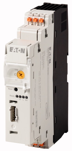
Ters yolverici, 24 V DC, 0,18 - 2,4 A, Basmalı terminaller, SmartWire-DT bağımlı Ters yolverici, Çalıştırma gerilimi: 24 V DC, Standartlar: IEC/EN 60947-4-2
Ters yolverici, 24 V DC, 0,18 - 2,4 A, Basmalı terminaller, SmartWire-DT bağımlı
Ters yolverici, Çalıştırma gerilimi: 24 V DC, Standartlar: IEC/EN 60947-4-2
| Product range | Electronic motor starter |
| Product range | SmartWire-DT slave |
| Subrange | SmartWire-DT electronic motor starters |
| Basic function | Reversing starters (complete devices) |
| Function | For connecting to SmartWire-DT for expanded diagnostics. |
| Description | DOL starting Reversing start Motor protection Circuit design: safety output stage with bypass, three-phase disconnect. Motor current additionally adjustable via SmartWire-DT. |
| Messages | Operational readiness Operating direction feedback Motor current in % Motor current in A Thermal motor image in % Overload prewarning Trip indications (overload, phase failure, etc.) Set short-circuit release value Device Type |
| Commands | Operating the motor starter Manual reset Automatic reset |
| Max. rating for three-phase motors, 50 - 60 Hz >AC-53a >380 V 400 V 415 V [P] |
0.06 - 0.75 kW |
| Setting range of overload releases |
0,18 - 2,4 A_x |
| Actuating voltage | 24 V DC |
| Connection technique | Push in terminals |
| Connection to SmartWire-DT | yes |
| Standards | IEC/EN 60947-4-2 |
| Dimensions >Width |
30 mm |
| Dimensions >Height |
157 mm |
| Dimensions >Depth |
124 mm |
| Weight | 0.3 kg |
| Mounting | Top-hat rail IEC/EN 60715, 35 mm |
| Protection type (IEC/EN 60529, EN50178, VBG 4) | IP20 |
| Mounting position | Vertical |
| Lifespan, electrical [Operations] | 3 x 10⁷ |
| Max. switching frequency | 7200 (pulse pause time 50:50) Operations/h |
| Terminal capacity >Solid |
1 x (0.2 - 2.5) 1 x AWG20 - 14 mm2 |
| Terminal capacity >flexible, with ferrule |
2 x (0,2 - 2,5) 1 x AWG24 - 14 mm2 |
| Terminal capacity >Notes |
Minimum length 10 mm. |
| Terminal capacity >flexible, with twin ferrule |
2 x (0,2 - 1,5) 2 x AWG24 - 16 mm2 |
| Terminal capacity >Notes |
Minimum length 10 mm. |
| Operating ambient temperature | -5 - +60, in accordance with IEC 60068-2-1 °C |
| Storage [ϑ] | -40 - +80 °C |
| Rated impulse withstand voltage [Uimp] | 6000 V AC |
| Overvoltage category/pollution degree | III/2 |
| Rated operational voltage [Ue ] | 42 - 550 V |
| Rated operational current >AC-51 [Ie] |
0.15 - 2.40 A |
| Rated operational current >AC-53a [Ie] |
0.15 - 2.4 A |
| Heat dissipation [PV] | 0.1 - 2 W |
| Static heat dissipation, non-current-dependent [Pvs] | 1 W |
| Basic insulation to IEC/EN60947-1 >between feedback signal output and switch voltage |
500 V AC |
| Current measurement >Setting range of overload releases |
0,18 - 2,4 A_x |
| Current measurement >Release class |
10 CLASS |
| Current measurement >Recovery time [tW] |
2 (manual startup) 20 (automatic restart) min. |
| Current measurement >Balance monitoring >Magnitude Imax > Irated ((Imax - Imin)/Imax) |
If ≧ 33, pick-up time of 120 s If ≧ 67, pick-up time of 1.8 s % |
| Current measurement >Balance monitoring >Magnitude Imax < Irated ((Imax - Imin)/Irated) |
If ≧ 33, pick-up time of 120 s If ≧ 67, pick-up time of 1.8 s % |
| Stall protection >Pick-up time I (L1) or I (L3) |
33 A |
| Stall protection >Pick-up time |
0.5 S |
| Short-circuit rating >Type “1” coordination >Short-circuit protective device |
50 kA, 500 V AC: Fuse 16 A gG/gL 50 kA, 500 V AC: fuse 30 A CCMR 50 kA, 415 V AC: PKM0-4 15 kA, 415 V AC: PKM0-6,3 2.5 kA, 400 V AC: FAZ-B16/3 |
| Input data >Supply voltage [UAUX] |
24 (-15 - +20 %) V DC |
| Input data >Residual ripple on the input voltage |
≦ 5 % |
| Input data >Input current |
70 mA |
| Input data >Current draw inrush |
120 mA |
| Input data >Current draw (operation) [UAUX] |
50 mA |
| Electrostatic discharge (ESD) >applied standard |
IEC EN 61000-4-2, Level 3 |
| Electrostatic discharge (ESD) >Air discharge |
8 kV |
| Electrostatic discharge (ESD) >Contact discharge |
6 kV |
| Electromagnetic fields (RFI) >applied standard |
IEC/EN 61000-4-3 |
| Electromagnetic fields (RFI) | 800 - 1000 MHz: 10 1.4 - 2 GHz: 10 2.0 - 2.7 GHz: 3 V/m |
| Radio interference suppression | EN 55011, Class A (emitted interference, line-conducted) EN 61000-6-3, Class A (emitted interference, radiated) |
| Note on use | This product is designed for operation in industrial environments (environment 2). The use in residential environments (environment 1) could cause electrical interference so that addition suppression must be planned. |
| Burst | 2 IEC/EN 61000-4-4, level 3 kV |
| power pulses (Surge) | 1 kV (symmetrical) 2 kV (asymmetrical) according to IEC/EN 61000-4-5 |
| Immunity to line-conducted interference to (IEC/EN 61000-4-6) | 10 V |
| Rated operational current for specified heat dissipation [In] | 2.4 A |
| Heat dissipation per pole, current-dependent [Pvid] | 0.7 W |
| Equipment heat dissipation, current-dependent [Pvid] | 2.1 W |
| Static heat dissipation, non-current-dependent [Pvs] | 1 W |
| Heat dissipation capacity [Pdiss] | 0 W |
| Operating ambient temperature min. | -5 °C |
| Operating ambient temperature max. | +60 °C |
| 10.2 Strength of materials and parts >10.2.2 Corrosion resistance |
Meets the product standard´s requirements. |
| 10.2 Strength of materials and parts >10.2.3.1 Verification of thermal stability of enclosures |
Meets the product standard´s requirements. |
| 10.2 Strength of materials and parts >10.2.3.2 Verification of resistance of insulating materials to normal heat |
Meets the product standard´s requirements. |
| 10.2 Strength of materials and parts >10.2.3.3 Verification of resistance of insulating materials to abnormal heat and fire due to internal electric effects |
Meets the product standard´s requirements. |
| 10.2 Strength of materials and parts >10.2.4 Resistance to ultra-violet (UV) radiation |
Meets the product standard´s requirements. |
| 10.2 Strength of materials and parts >10.2.5 Lifting |
Does not apply, since the entire switchgear needs to be evaluated. |
| 10.2 Strength of materials and parts >10.2.6 Mechanical impact |
Does not apply, since the entire switchgear needs to be evaluated. |
| 10.2 Strength of materials and parts >10.2.7 Inscriptions |
Meets the product standard´s requirements. |
| 10.3 Degree of protection of ASSEMBLIES | Does not apply, since the entire switchgear needs to be evaluated. |
| 10.4 Clearances and creepage distances | Meets the product standard´s requirements. |
| 10.5 Protection against electric shock | Does not apply, since the entire switchgear needs to be evaluated. |
| 10.6 Incorporation of switching devices and components | Does not apply, since the entire switchgear needs to be evaluated. |
| 10.7 Internal electrical circuits and connections | Is the panel builder´s responsibility. |
| 10.8 Connections for external conductors | Is the panel builder´s responsibility. |
| 10.9 Insulation properties >10.9.2 Power-frequency electric strength |
Is the panel builder´s responsibility. |
| 10.9 Insulation properties >10.9.3 Impulse withstand voltage |
Is the panel builder´s responsibility. |
| 10.9 Insulation properties >10.9.4 Testing of enclosures made of insulating material |
Is the panel builder´s responsibility. |
| 10.10 Temperature rise | The panel builder is responsible for the temperature rise calculation. Eaton will provide heat dissipation data for the devices. |
| 10.11 Short-circuit rating | Is the panel builder´s responsibility. The specifications for the switchgear must be observed. |
| 10.12 Electromagnetic compatibility | Is the panel builder´s responsibility. The specifications for the switchgear must be observed. |
| 10.13 Mechanical function | The device meets the requirements, provided the information in the instruction leaflet (IL) is observed. |
| Kind of motor starter | Reversing starter |
| With short-circuit release | No |
| Rated control supply voltage Us at AC 50HZ | 0 - 0 V |
| Rated control supply voltage Us at AC 60HZ | 0 - 0 V |
| Rated control supply voltage Us at DC | 24 - 24 V |
| Voltage type for actuating | DC |
| Rated operation power at AC-3, 230 V, 3-phase | 0.37 kW |
| Rated operation power at AC-3, 400 V | 0.75 kW |
| Rated power, 460 V, 60 Hz, 3-phase | 0.736 kW |
| Rated power, 575 V, 60 Hz, 3-phase | 0 kW |
| Rated operation current Ie | 2.4 A |
| Rated operation current at AC-3, 400 V | 2.4 A |
| Overload release current setting | 0.18 - 2.4 A |
| Rated conditional short-circuit current, type 1, 480 Y/277 V | 0 A |
| Rated conditional short-circuit current, type 1, 600 Y/347 V | 0 A |
| Rated conditional short-circuit current, type 2, 230 V | 0 A |
| Rated conditional short-circuit current, type 2, 400 V | 0 A |
| Number of auxiliary contacts as normally open contact | 0 |
| Number of auxiliary contacts as normally closed contact | 0 |
| Ambient temperature, upper operating limit | 60 °C |
| Temperature compensated overload protection | Yes |
| Release class | CLASS 10 |
| Type of electrical connection of main circuit | Spring clamp connection |
| Type of electrical connection for auxiliary- and control current circuit | Spring clamp connection |
| Rail mounting possible | Yes |
| With transformer | No |
| Number of command positions | 0 |
| Suitable for emergency stop | No |
| Coordination class according to IEC 60947-4-3 | Class 1 |
| Number of indicator lights | 4 |
| External reset possible | Yes |
| With fuse | No |
| Degree of protection (IP) | IP20 |
| Degree of protection (NEMA) | Other |
| Supporting protocol for TCP/IP | No |
| Supporting protocol for PROFIBUS | No |
| Supporting protocol for CAN | No |
| Supporting protocol for INTERBUS | No |
| Supporting protocol for ASI | No |
| Supporting protocol for MODBUS | No |
| Supporting protocol for Data-Highway | No |
| Supporting protocol for DeviceNet | No |
| Supporting protocol for SUCONET | No |
| Supporting protocol for LON | No |
| Supporting protocol for PROFINET IO | No |
| Supporting protocol for PROFINET CBA | No |
| Supporting protocol for SERCOS | No |
| Supporting protocol for Foundation Fieldbus | No |
| Supporting protocol for EtherNet/IP | No |
| Supporting protocol for AS-Interface Safety at Work | No |
| Supporting protocol for DeviceNet Safety | No |
| Supporting protocol for INTERBUS-Safety | No |
| Supporting protocol for PROFIsafe | No |
| Supporting protocol for SafetyBUS p | No |
| Supporting protocol for other bus systems | Yes |
| Width | 30 mm |
| Height | 157 mm |
| Depth | 139 mm |
| Product Standards | IEC/EN 60947-5; UL 508; CSA-C22.2 No. 14; CE marking |
| UL File No. | E29096 |
| UL Category Control No. | NLDX, NLDX7 |
| CSA File No. | UL report applies to both US and Canada |
| North America Certification | UL listed, certified by UL for use in Canada |
| Specially designed for North America | No |
| Characteristic curve |
Mnelko olarak, endüstriyel otomasyon çözümlerinde güvenilir bir iş ortağı olarak, geniş ürün yelpazesi ile işletmenizin tüm ihtiyaçlarını karşılamaya yönelik kaliteli ve yenilikçi ürünler sunmaktayız. Ürün portföyümüz, modern endüstriyel süreçleri desteklemek amacıyla yüksek performans, dayanıklılık ve verimlilik ilkeleri doğrultusunda tasarlanmış çözümlerden oluşur.
Tüm ürünlerimiz, zorlu çalışma koşullarında dahi maksimum güvenilirlik sunar ve işletmenizin operasyonlarını sorunsuz şekilde sürdürmesine yardımcı olur. Endüstriyel otomasyon, enerji yönetimi, kablolama çözümleri ve daha birçok alanda sunduğumuz ürünler, farklı sektörlerdeki ihtiyaçlara esneklikle uyum sağlar.
Ayrıca, ürünlerimiz sadece kaliteli malzemelerle üretilmiş olup, uluslararası standartlara uygunluk göstermektedir. Müşterilerimize sunduğumuz çözümlerle, operasyonel verimliliklerini artırmalarına ve maliyetlerini optimize etmelerine olanak tanıyoruz. Teknolojik gelişmeleri yakından takip eden firmamız, sürekli olarak yenilikçi ürünler sunarak, müşterilerimizin rekabet avantajı elde etmesine destek vermektedir.
Her bir ürün sayfamızda, teknik detaylar, kullanım alanları ve ürün özelliklerine dair kapsamlı bilgilere ulaşabilirsiniz. Endüstriyel süreçlerinizi güçlendirmek için ihtiyacınız olan tüm ürünleri sitemizden keşfedebilir, sorunsuz bir satın alma deneyimi yaşayabilirsiniz.
Benzer Ürünler


Aradığınız ürünü bulamıyor musunuz?
SİZE YARDIMCI OLALIM
Aradığınız Ürünü Bulamadınız mı? Bize Bildirin, Sizin İçin Tedarik Edelim!
Web sitemizde yer almayan ya da stokta bulunmayan ürünleri mi arıyorsunuz? İhtiyacınızı bize bildirin, uzman ekibimiz en kısa sürede sizinle iletişime geçerek size en uygun çözümü bulsun.