Eaton : DILM150-XHI40
277948 DILM150-XHI40
DILM150-XHI40 /277948
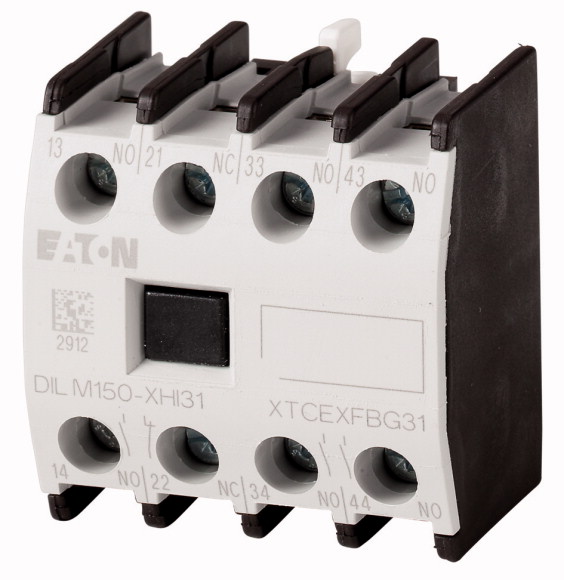
Yardımcı kontak modülü, 4 kutuplu, Ith= 16 A, 4 N/O, Önden sabitleme, Vidalı terminaller, DILM40 - DILM170 Yardımcı kontak modülü, kilitli karşılıklı kontaklarla, Fonksiyon: standart uygulamalar için, 4 kutuplu, Bağlantı tekniği: Vidalı terminaller, Nominal çalışma akımı AC-15 220 V 230 V 240 V: Ie= 6 A, Nominal çalışma akımı AC-15 380 V 400 V 415 V: Ie= 4 A, Kontaklar N/O = Normalde açık: 4 N/O, Montaj tipi: Önden sabitleme, Şunlarla kullanım için: DILM40…, DILM50…, DILM65…, DILM72…, DILM80…, DILM95… , DILM115…, DILM150…, DILM170…, DILMP63…, DILMP80…, DILMP125…, DILMP160…, DILMP200…, DILMF40…, DILMF50…, DILMF65…, DILMF80…, DILMF95…, DILMF115…, DILMF150…, Tip: Önden montaj yardımcı kontak, Talimatlar: IEC/EN 60947-5-1 Ek L'ye göre kilitli karşılıklı kontaklar, yardımcı kontak modülünün içinde, IEC/EN 60947-4-1 Ek F'ye göre ayna kontakları olarak kullanılan yardımcı kontaklar (N/C değil) geç açık)
Yardımcı kontak modülü, 4 kutuplu, Ith= 16 A, 4 N/O, Önden sabitleme, Vidalı terminaller, DILM40 - DILM170
Yardımcı kontak modülü, kilitli karşılıklı kontaklarla, Fonksiyon: standart uygulamalar için, 4 kutuplu, Bağlantı tekniği: Vidalı terminaller, Nominal çalışma akımı AC-15 220 V 230 V 240 V: Ie= 6 A, Nominal çalışma akımı AC-15 380 V 400 V 415 V: Ie= 4 A, Kontaklar N/O = Normalde açık: 4 N/O, Montaj tipi: Önden sabitleme, Şunlarla kullanım için: DILM40…, DILM50…, DILM65…, DILM72…, DILM80…, DILM95… , DILM115…, DILM150…, DILM170…, DILMP63…, DILMP80…, DILMP125…, DILMP160…, DILMP200…, DILMF40…, DILMF50…, DILMF65…, DILMF80…, DILMF95…, DILMF115…, DILMF150…, Tip: Önden montaj yardımcı kontak, Talimatlar: IEC/EN 60947-5-1 Ek L'ye göre kilitli karşılıklı kontaklar, yardımcı kontak modülünün içinde, IEC/EN 60947-4-1 Ek F'ye göre ayna kontakları olarak kullanılan yardımcı kontaklar (N/C değil) geç açık)
| Accessories | Auxiliary contact modules |
| Description | with interlocked opposing contacts |
| Function | for standard applications |
| Number of poles | 4 pole |
| Connection technique | Screw terminals |
| Conventional free air thermal current, 1 pole >Open >at 60 °C [Ith] |
|
| AC-15 >220 V 230 V 240 V [Ie] |
16 A |
| AC-15 >380 V 400 V 415 V [Ie] |
6 A |
| N/O = Normally open | 4 A |
| Mounting type | |
| Contact sequence | 4 N/O |
| For use with | Front fixing |
| Type | |
| Instructions | DILM40… DILM50… DILM65… DILM72… DILM80… DILM95… DILM115… DILM150… DILM170… DILMP63… DILMP80… DILMP125… DILMP160… DILMP200… DILMF40… DILMF50… DILMF65… DILMF80… DILMF95… DILMF115… DILMF150… |
| Standards | Front mounting auxiliary contact |
| Component lifespan >at Ue = 230 V, AC-15, 3 A [Operations] |
Interlocked opposing contacts according to IEC/EN 60947-5-1 Appendix L, inside the auxiliary contact module Auxiliary contacts used as mirror contacts according to IEC/EN 60947-4-1 Appendix F (not N/C late open) |
| Climatic proofing | |
| Ambient temperature >Open |
IEC/EN 60947, VDE 0660, UL, CSA |
| Ambient temperature >Enclosed |
1.3 x 10⁶ |
| Ambient temperature >Ambient temperature, storage |
Damp heat, constant, to IEC 60068-2-78 Damp heat, cyclic, to IEC 60068-2-30 |
| Mechanical shock resistance (IEC/EN 60068-2-27) >Half-sinusoidal shock, 10 ms >Basic unit with auxiliary contact module >N/O contact |
-25 - +60 °C |
| Mechanical shock resistance (IEC/EN 60068-2-27) >Half-sinusoidal shock, 10 ms >Basic unit with auxiliary contact module >N/C contact |
- 25 - 40 °C |
| Degree of Protection | - 40 - 80 °C |
| Protection against direct contact when actuated from front (EN 50274) | 7 g |
| Weight | 5 g |
| Terminal capacities >Screw terminals >Solid |
IP20 |
| Terminal capacities >Screw terminals >Flexible with ferrule |
Finger and back-of-hand proof |
| Terminal capacities >Screw terminals >Solid or stranded |
0.055 kg |
| Terminal capacities >Screw terminals >Pozidriv screwdriver |
1 x (0.75 - 2.5) 2 x (0.75 - 2.5) mm2 |
| Terminal capacities >Screw terminals >Standard screwdriver |
1 x (0.75 - 2.5) 2 x (0.75 - 2.5) mm2 |
| Terminal capacities >Screw terminals >Max. tightening torque |
18 – 14 AWG |
| Interlocked opposing contacts within an auxiliary contact module (to IEC 60947-5-1 Annex L) | 2 Size |
| N/C contact (not late-break contact) suitable as a mirror contact (to IEC/EN 60947-4-1 Annex F) | 0.8 x 5.5 1 x 6 mm |
| Rated impulse withstand voltage [Uimp] | 1.2 Nm |
| Overvoltage category/pollution degree | |
| Rated insulation voltage [Ui] | Yes |
| Rated operational voltage [Ue] | DILM40 - DILM170 |
| Safe isolation to EN 61140 >between coil and auxiliary contacts |
6000 V AC |
| Safe isolation to EN 61140 >between the auxiliary contacts |
III/3 |
| Rated operational current >Conventional free air thermal current, 1 pole >at 60 °C [Ith] |
690 V AC |
| Rated operational current >AC-15 >220 V 230 V 240 V [Ie] |
500 V AC |
| Rated operational current >AC-15 >380 V 400 V 415 V [Ie] |
440 V AC |
| Rated operational current >AC-15 >500 V [Ie] |
440 V AC |
| Rated operational current >DC current |
16 A |
| Rated operational current >DC current >DC L/R ≦ 15 ms >Contacts in series: >1 [24 V] |
6 A |
| Rated operational current >DC current >DC L/R ≦ 15 ms >Contacts in series: >1 [60 V] |
4 A |
| Rated operational current >DC current >DC L/R ≦ 15 ms >Contacts in series: >1 [110 V] |
1.5 A |
| Rated operational current >DC current >DC L/R ≦ 15 ms >Contacts in series: >1 [220 V] |
Switch-on and switch-off conditions based on DC-13, time constant as specified. |
| Rated operational current >Control circuit reliability [Failure rate] |
10 A |
| Short-circuit rating without welding >Short-circuit protection maximum fuse >500 V |
6 A |
| Current heat loss at Ith >AC operated |
3 A |
| Current heat loss at Ith >DC operated |
1 A |
| Current heat loss at Ith >Current heat loss per auxiliary circuit at Ie (AC-15/230 V) |
<10-8, < one failure at 100 million operations (at Ue = 24 V DC, Umin = 17 V, Imin = 5.4 mA) λ |
| Auxiliary contacts >Pilot Duty >AC operated |
16 A gG/gL |
| Auxiliary contacts >Pilot Duty >DC operated |
3.7 W |
| Auxiliary contacts >General Use >AC |
3.7 W |
| Auxiliary contacts >General Use >AC |
0.5 CO |
| Auxiliary contacts >General Use >DC |
|
| Auxiliary contacts >General Use >DC |
A600 |
| Rated operational current for specified heat dissipation [In] | P300 |
| Heat dissipation per pole, current-dependent [Pvid] | 600 V |
| Equipment heat dissipation, current-dependent [Pvid] | 15 A |
| Static heat dissipation, non-current-dependent [Pvs] | 250 V |
| Heat dissipation capacity [Pdiss] | 1 A |
| Operating ambient temperature min. | |
| Operating ambient temperature max. | 4 A |
| 10.2 Strength of materials and parts >10.2.2 Corrosion resistance |
0.23 W |
| 10.2 Strength of materials and parts >10.2.3.1 Verification of thermal stability of enclosures |
0 W |
| 10.2 Strength of materials and parts >10.2.3.2 Verification of resistance of insulating materials to normal heat |
0 W |
| 10.2 Strength of materials and parts >10.2.3.3 Verification of resistance of insulating materials to abnormal heat and fire due to internal electric effects |
0 W |
| 10.2 Strength of materials and parts >10.2.4 Resistance to ultra-violet (UV) radiation |
-25 °C |
| 10.2 Strength of materials and parts >10.2.5 Lifting |
+60 °C |
| 10.2 Strength of materials and parts >10.2.6 Mechanical impact |
|
| 10.2 Strength of materials and parts >10.2.7 Inscriptions |
Meets the product standard´s requirements. |
| 10.3 Degree of protection of ASSEMBLIES | Meets the product standard´s requirements. |
| 10.4 Clearances and creepage distances | Meets the product standard´s requirements. |
| 10.5 Protection against electric shock | Meets the product standard´s requirements. |
| 10.6 Incorporation of switching devices and components | Meets the product standard´s requirements. |
| 10.7 Internal electrical circuits and connections | Does not apply, since the entire switchgear needs to be evaluated. |
| 10.8 Connections for external conductors | Does not apply, since the entire switchgear needs to be evaluated. |
| 10.9 Insulation properties >10.9.2 Power-frequency electric strength |
Meets the product standard´s requirements. |
| 10.9 Insulation properties >10.9.3 Impulse withstand voltage |
Does not apply, since the entire switchgear needs to be evaluated. |
| 10.9 Insulation properties >10.9.4 Testing of enclosures made of insulating material |
Meets the product standard´s requirements. |
| 10.10 Temperature rise | Does not apply, since the entire switchgear needs to be evaluated. |
| 10.11 Short-circuit rating | Does not apply, since the entire switchgear needs to be evaluated. |
| 10.12 Electromagnetic compatibility | Is the panel builder´s responsibility. |
| 10.13 Mechanical function | Is the panel builder´s responsibility. |
| Number of contacts as change-over contact | Is the panel builder´s responsibility. |
| Number of contacts as normally open contact | Is the panel builder´s responsibility. |
| Number of contacts as normally closed contact | Is the panel builder´s responsibility. |
| Number of fault-signal switches | The panel builder is responsible for the temperature rise calculation. Eaton will provide heat dissipation data for the devices. |
| Rated operation current Ie at AC-15, 230 V | Is the panel builder´s responsibility. The specifications for the switchgear must be observed. |
| Type of electric connection | Is the panel builder´s responsibility. The specifications for the switchgear must be observed. |
| Model | The device meets the requirements, provided the information in the instruction leaflet (IL) is observed. |
| Mounting method | |
| Lamp holder | |
| Product Standards | 0 |
| UL File No. | 4 |
| UL Category Control No. | 0 |
| CSA File No. | 0 |
| CSA Class No. | 6 A |
| North America Certification | Screw connection |
| Specially designed for North America | Top mounting |
Tüm ürünlerimiz, zorlu çalışma koşullarında dahi maksimum güvenilirlik sunar ve işletmenizin operasyonlarını sorunsuz şekilde sürdürmesine yardımcı olur. Endüstriyel otomasyon, enerji yönetimi, kablolama çözümleri ve daha birçok alanda sunduğumuz ürünler, farklı sektörlerdeki ihtiyaçlara esneklikle uyum sağlar.
Ayrıca, ürünlerimiz sadece kaliteli malzemelerle üretilmiş olup, uluslararası standartlara uygunluk göstermektedir. Müşterilerimize sunduğumuz çözümlerle, operasyonel verimliliklerini artırmalarına ve maliyetlerini optimize etmelerine olanak tanıyoruz. Teknolojik gelişmeleri yakından takip eden firmamız, sürekli olarak yenilikçi ürünler sunarak, müşterilerimizin rekabet avantajı elde etmesine destek vermektedir.
Her bir ürün sayfamızda, teknik detaylar, kullanım alanları ve ürün özelliklerine dair kapsamlı bilgilere ulaşabilirsiniz. Endüstriyel süreçlerinizi güçlendirmek için ihtiyacınız olan tüm ürünleri sitemizden keşfedebilir, sorunsuz bir satın alma deneyimi yaşayabilirsiniz.
Benzer Ürünler


Aradığınız ürünü bulamıyor musunuz?
SİZE YARDIMCI OLALIM
Aradığınız Ürünü Bulamadınız mı? Bize Bildirin, Sizin İçin Tedarik Edelim!
Web sitemizde yer almayan ya da stokta bulunmayan ürünleri mi arıyorsunuz? İhtiyacınızı bize bildirin, uzman ekibimiz en kısa sürede sizinle iletişime geçerek size en uygun çözümü bulsun.