Eaton : DILH2600/22(RAW250)
125945 DILH2600/22(RAW250)
DILH2600/22(RAW250) /125945
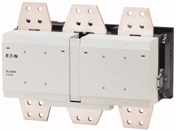
Kontaktör, Ith =Ie: 3185 A, RAW 250: 230 - 250 V 50 - 60 Hz/230 - 350 V DC, AC ve DC çalışma, Vidalı bağlantı Kontaktör, Uygulama: 1000 A'den itibaren dirençli yükler için şebeke kontaktörleri, 1000 A'dan büyük AC -1 kontaktörler, Kullanım kategorisi: AC-1: Endüktif olmayan veya hafif endüktif yükler, direnç fırınları, Bağlantı tekniği: Vidalı bağlantı, Nominal çalışma akımı AC -1 Konvansiyonel serbest hava termik akımı, 3 kutuplu, 50 - 60 Hz 40 °C'de açık: Ith =Ie= 3185 A, Nominal çalışma akımı AC-1 Konvansiyonel serbest hava termik akımı, 1 kutup açık: Ith= 6500 A, For Şunlarla kullanın: DILM820-XHI…, Talimatlar: Çalıştırma elektroniğinde entegre baskılayıcı devre, 660 V, 690 V veya 1000 V: doğrudan yön değiştirmeyen, Gerilim AC/DC: AC ve DC çalışması
Kontaktör, Ith =Ie: 3185 A, RAW 250: 230 - 250 V 50 - 60 Hz/230 - 350 V DC, AC ve DC çalışma, Vidalı bağlantı
Kontaktör, Uygulama: 1000 A'den itibaren dirençli yükler için şebeke kontaktörleri, 1000 A'dan büyük AC -1 kontaktörler, Kullanım kategorisi: AC-1: Endüktif olmayan veya hafif endüktif yükler, direnç fırınları, Bağlantı tekniği: Vidalı bağlantı, Nominal çalışma akımı AC -1 Konvansiyonel serbest hava termik akımı, 3 kutuplu, 50 - 60 Hz 40 °C'de açık: Ith =Ie= 3185 A, Nominal çalışma akımı AC-1 Konvansiyonel serbest hava termik akımı, 1 kutup açık: Ith= 6500 A, For Şunlarla kullanın: DILM820-XHI…, Talimatlar: Çalıştırma elektroniğinde entegre baskılayıcı devre, 660 V, 690 V veya 1000 V: doğrudan yön değiştirmeyen, Gerilim AC/DC: AC ve DC çalışması
| Product range | Contactors | |||||||||||||||||||||||
| Application | Mains contactors for resistive loads from 1000 A | |||||||||||||||||||||||
| Subrange | AC -1 contactors greater than 1000 A | |||||||||||||||||||||||
| Utilization category | AC-1: Non-inductive or slightly inductive loads, resistance furnaces | |||||||||||||||||||||||
| Connection technique | Screw connection | |||||||||||||||||||||||
| AC-1 >Conventional free air thermal current, 3 pole, 50 - 60 Hz >Open >at 40 °C [Ith =Ie] |
||||||||||||||||||||||||
| AC-1 >Conventional free air thermal current, 1 pole >open [Ith ] |
3185 A | |||||||||||||||||||||||
| Contact sequence | 6500 A | |||||||||||||||||||||||
| For use with | ||||||||||||||||||||||||
| Actuating voltage | DILM820-XHI… | |||||||||||||||||||||||
| Voltage AC/DC | RAW 250: 230 - 250 V 50 - 60 Hz/230 - 350 V DC | |||||||||||||||||||||||
| possible variants at auxiliary contact module fitting options | AC and DC operation | |||||||||||||||||||||||
| Side mounting auxiliary contacts | ||||||||||||||||||||||||
| Instructions | on the side: 2 x DILM820-XHI11(V)-SI; 2 x DILM820-XHI11-SA | |||||||||||||||||||||||
| Instructions | ||||||||||||||||||||||||
| Note concerning the product | Interlocked opposing contacts according to IEC/EN 60947-5-1 Appendix L, inside the auxiliary contact module Auxiliary contacts used as mirror contacts according to IEC/EN 60947-4-1 Appendix F (not N/C late open) |
|||||||||||||||||||||||
| Standards | integrated suppressor circuit in actuating electronics 660 V, 690 V or 1000 V: not directly reversing |
|||||||||||||||||||||||
| Lifespan, mechanical >AC operated [Operations] |
|
|||||||||||||||||||||||
| Lifespan, mechanical >DC operated [Operations] |
||||||||||||||||||||||||
| Operating frequency, mechanical >AC operated [Operations/h] |
IEC/EN 60947, VDE 0660, UL, CSA, CCC | |||||||||||||||||||||||
| Operating frequency, mechanical >DC operated [Operations/h] |
5 x 10⁶ | |||||||||||||||||||||||
| Climatic proofing | 5 x 10⁶ | |||||||||||||||||||||||
| Ambient temperature >Open |
1000 | |||||||||||||||||||||||
| Ambient temperature >Storage |
1000 | |||||||||||||||||||||||
| Mounting position | Damp heat, constant, to IEC 60068-2-78 Damp heat, cyclic, to IEC 60068-2-30 |
|||||||||||||||||||||||
| Mechanical shock resistance (IEC/EN 60068-2-27) >Half-sinusoidal shock, 10 ms >Main contacts >N/O contact |
-40 - +60 °C | |||||||||||||||||||||||
| Mechanical shock resistance (IEC/EN 60068-2-27) >Half-sinusoidal shock, 10 ms >Auxiliary contacts >N/O contact |
- 40 - + 80 °C | |||||||||||||||||||||||
| Mechanical shock resistance (IEC/EN 60068-2-27) >Half-sinusoidal shock, 10 ms >Auxiliary contacts >N/C contact |
||||||||||||||||||||||||
| Degree of Protection | 10 g | |||||||||||||||||||||||
| Altitude | 10 g | |||||||||||||||||||||||
| Weight | 8 g | |||||||||||||||||||||||
| Terminal capacity main cable >Busbar [Width] |
IP00 | |||||||||||||||||||||||
| Main cable connection screw/bolt | Max. 2000 m | |||||||||||||||||||||||
| Tightening torque | 35.2 kg | |||||||||||||||||||||||
| Terminal capacity control circuit cables >Solid |
100 mm | |||||||||||||||||||||||
| Terminal capacity control circuit cables >Flexible with ferrule |
M12 | |||||||||||||||||||||||
| Terminal capacity control circuit cables >Solid or stranded |
35 Nm | |||||||||||||||||||||||
| Stripping length | 1 x (0.75 - 2.5) 2 x (0.75 - 2.5) mm2 |
|||||||||||||||||||||||
| Control circuit cable connection screw/bolt | 1 x (0.75 - 2.5) 2 x (0.75 - 2.5) mm2 |
|||||||||||||||||||||||
| Tightening torque | 18 - 14 AWG | |||||||||||||||||||||||
| Tool >Main cable >Width across flats |
10 mm | |||||||||||||||||||||||
| Tool >Control circuit cables >Pozidriv screwdriver |
M3.5 | |||||||||||||||||||||||
| Tool >Control circuit cables >Standard screwdriver |
1.2 Nm | |||||||||||||||||||||||
| Rated impulse withstand voltage [Uimp] | 18 mm | |||||||||||||||||||||||
| Overvoltage category/pollution degree | 2 Size | |||||||||||||||||||||||
| Rated insulation voltage [Ui] | 0.8 x 5.5/1 x 6 mm | |||||||||||||||||||||||
| Rated operational voltage [Ue] | ||||||||||||||||||||||||
| Safe isolation to EN 61140 >between coil and contacts |
8000 V AC | |||||||||||||||||||||||
| Safe isolation to EN 61140 >between the contacts |
III/3 | |||||||||||||||||||||||
| Making capacity (p.f. to IEC/EN 60947) | 1000 V AC | |||||||||||||||||||||||
| Breaking capacity >220 V 230 V |
1000 V AC | |||||||||||||||||||||||
| Breaking capacity >380 V 400 V |
500 V AC | |||||||||||||||||||||||
| Breaking capacity >500 V |
500 V AC | |||||||||||||||||||||||
| Breaking capacity >660 V 690 V |
9840 A | |||||||||||||||||||||||
| Breaking capacity >1000 V |
8200 A | |||||||||||||||||||||||
| Component lifespan | 8200 A | |||||||||||||||||||||||
| AC-1 >Rated operational current >Conventional free air thermal current, 3 pole, 50 - 60 Hz >Open >at 40 °C [Ith =Ie] |
8200 A | |||||||||||||||||||||||
| AC-1 >Rated operational current >Conventional free air thermal current, 3 pole, 50 - 60 Hz >Open >at 50 °C [Ith =Ie] |
8200 A | |||||||||||||||||||||||
| AC-1 >Rated operational current >Conventional free air thermal current, 3 pole, 50 - 60 Hz >Open >at 55 °C [Ith =Ie] |
5800 A | |||||||||||||||||||||||
| AC-1 >Rated operational current >Conventional free air thermal current, 3 pole, 50 - 60 Hz >Open >at 60 °C [Ith =Ie] |
AC1: See → Engineering, characteristic curves | |||||||||||||||||||||||
| AC-1 >Rated operational current >Conventional free air thermal current, 1 pole >Note |
||||||||||||||||||||||||
| AC-1 >Rated operational current >Conventional free air thermal current, 1 pole >open [Ith ] |
3185 A | |||||||||||||||||||||||
| 3 pole, at Ith (60°) | 2847 A | |||||||||||||||||||||||
| Current heat loss at Ie to AC-3/400 V | 2716 A | |||||||||||||||||||||||
| Voltage tolerance >US |
2600 A | |||||||||||||||||||||||
| Voltage tolerance >AC operated [Pick-up] |
at maximum permissible ambient air temperature | |||||||||||||||||||||||
| Voltage tolerance >DC operated [Pick-up] |
6500 A | |||||||||||||||||||||||
| Voltage tolerance >AC operated [Drop-out] |
||||||||||||||||||||||||
| Voltage tolerance >DC operated [Drop-out] |
249 W | |||||||||||||||||||||||
| Power consumption of the coil in a cold state and 1.0 x US >Note on power consumption |
0.012 W | |||||||||||||||||||||||
| Power consumption of the coil in a cold state and 1.0 x US >Pull-in power [Pick-up] |
||||||||||||||||||||||||
| Power consumption of the coil in a cold state and 1.0 x US >Pull-in power [Pick-up] |
230 - 250 V 50/60 Hz 230 - 350 V DC |
|||||||||||||||||||||||
| Power consumption of the coil in a cold state and 1.0 x US >Sealing power [Sealing] |
0.7 x US min - 1.15 x US max | |||||||||||||||||||||||
| Power consumption of the coil in a cold state and 1.0 x US >Sealing power [Sealing] |
0.7 x US min - 1.15 x US max | |||||||||||||||||||||||
| Duty factor | 0.2 x US max - 0.6 x US min | |||||||||||||||||||||||
| Changeover time at 100 % US (recommended value) >Main contacts >Closing delay |
0.2 x US max - 0.6 x US min | |||||||||||||||||||||||
| Changeover time at 100 % US (recommended value) >Main contacts >Opening delay |
Control transformer with uk ≦ 7% | |||||||||||||||||||||||
| Behaviour in marginal and transitional conditions >Sealing >Voltage interruptions >(0 … 0.2 x Uc min) ≦ 10 ms |
1600 VA | |||||||||||||||||||||||
| Behaviour in marginal and transitional conditions >Sealing >Voltage interruptions >(0 … 0.2 x Uc min) > 10 ms |
1400 W | |||||||||||||||||||||||
| Behaviour in marginal and transitional conditions >Sealing >Voltage drops >(0.2 … 0.6 x Uc min) ≦ 12 ms |
36.5 VA | |||||||||||||||||||||||
| Behaviour in marginal and transitional conditions >Sealing >Voltage drops >(0.2 … 0.6 x Uc min) > 12 ms |
17.3 W | |||||||||||||||||||||||
| Behaviour in marginal and transitional conditions >Sealing >Voltage drops >(0.6 … 0.7 x Uc min) |
100 % DF | |||||||||||||||||||||||
| Behaviour in marginal and transitional conditions >Sealing >Excess voltage >(1.15 … 1.3 x Uc max) |
70 ms | |||||||||||||||||||||||
| Behaviour in marginal and transitional conditions >Sealing >Pick-up phase >(0 … 0.7 x Uc min) |
40 ms | |||||||||||||||||||||||
| Behaviour in marginal and transitional conditions >Sealing >Pick-up phase >(0.7 x Uc min … 1.15 x Uc max) |
Time is bridged successfully | |||||||||||||||||||||||
| Admissible transitional contact resistance (of the external control circuit device when actuating A11) | Drop-out of the contactor | |||||||||||||||||||||||
| PLC signal level (A3 - A4) to IEC/EN 61131-2 (type 2) >High |
Time is bridged successfully | |||||||||||||||||||||||
| PLC signal level (A3 - A4) to IEC/EN 61131-2 (type 2) >Low |
Drop-out of the contactor | |||||||||||||||||||||||
| Electromagnetic compatibility | Contactor remains switched on | |||||||||||||||||||||||
| Switching capacity >General use |
Contactor remains switched on | |||||||||||||||||||||||
| Auxiliary contacts >Pilot Duty >AC operated |
Contactor does not switch on | |||||||||||||||||||||||
| Auxiliary contacts >Pilot Duty >DC operated |
Contactor switches on with certainty | |||||||||||||||||||||||
| Auxiliary contacts >General Use >AC |
≦ 500 mΩ | |||||||||||||||||||||||
| Auxiliary contacts >General Use >AC |
15 V | |||||||||||||||||||||||
| Auxiliary contacts >General Use >DC |
5 V | |||||||||||||||||||||||
| Auxiliary contacts >General Use >DC |
||||||||||||||||||||||||
| Special Purpose Ratings >Resistance Air Heating >480V 60Hz 3phase, 277V 60Hz 1phase |
This product is designed for operation in industrial environments (environment A). Its use in residential environments (environment B) may cause radio-frequency interference, requiring additional noise suppression measures. | |||||||||||||||||||||||
| Special Purpose Ratings >Resistance Air Heating >600V 60Hz 3phase, 347V 60Hz 1phase |
||||||||||||||||||||||||
| Rated operational current for specified heat dissipation [In] | 2600 A | |||||||||||||||||||||||
| Heat dissipation per pole, current-dependent [Pvid] | A600 | |||||||||||||||||||||||
| Equipment heat dissipation, current-dependent [Pvid] | P300 | |||||||||||||||||||||||
| Static heat dissipation, non-current-dependent [Pvs] | 600 V | |||||||||||||||||||||||
| Heat dissipation capacity [Pdiss] | 15 A | |||||||||||||||||||||||
| Operating ambient temperature min. | 250 V | |||||||||||||||||||||||
| Operating ambient temperature max. | 1 A | |||||||||||||||||||||||
| 10.2 Strength of materials and parts >10.2.2 Corrosion resistance |
2600 A | |||||||||||||||||||||||
| 10.2 Strength of materials and parts >10.2.3.1 Verification of thermal stability of enclosures |
2600 A | |||||||||||||||||||||||
| 10.2 Strength of materials and parts >10.2.3.2 Verification of resistance of insulating materials to normal heat |
||||||||||||||||||||||||
| 10.2 Strength of materials and parts >10.2.3.3 Verification of resistance of insulating materials to abnormal heat and fire due to internal electric effects |
2600 A | |||||||||||||||||||||||
| 10.2 Strength of materials and parts >10.2.4 Resistance to ultra-violet (UV) radiation |
83 W | |||||||||||||||||||||||
| 10.2 Strength of materials and parts >10.2.5 Lifting |
0 W | |||||||||||||||||||||||
| 10.2 Strength of materials and parts >10.2.6 Mechanical impact |
13 W | |||||||||||||||||||||||
| 10.2 Strength of materials and parts >10.2.7 Inscriptions |
0 W | |||||||||||||||||||||||
| 10.3 Degree of protection of ASSEMBLIES | -40 °C | |||||||||||||||||||||||
| 10.4 Clearances and creepage distances | +60 °C | |||||||||||||||||||||||
| 10.5 Protection against electric shock | ||||||||||||||||||||||||
| 10.6 Incorporation of switching devices and components | Meets the product standard´s requirements. | |||||||||||||||||||||||
| 10.7 Internal electrical circuits and connections | Meets the product standard´s requirements. | |||||||||||||||||||||||
| 10.8 Connections for external conductors | Meets the product standard´s requirements. | |||||||||||||||||||||||
| 10.9 Insulation properties >10.9.2 Power-frequency electric strength |
Meets the product standard´s requirements. | |||||||||||||||||||||||
| 10.9 Insulation properties >10.9.3 Impulse withstand voltage |
Meets the product standard´s requirements. | |||||||||||||||||||||||
| 10.9 Insulation properties >10.9.4 Testing of enclosures made of insulating material |
Does not apply, since the entire switchgear needs to be evaluated. | |||||||||||||||||||||||
| 10.10 Temperature rise | Does not apply, since the entire switchgear needs to be evaluated. | |||||||||||||||||||||||
| 10.11 Short-circuit rating | Meets the product standard´s requirements. | |||||||||||||||||||||||
| 10.12 Electromagnetic compatibility | Does not apply, since the entire switchgear needs to be evaluated. | |||||||||||||||||||||||
| 10.13 Mechanical function | Meets the product standard´s requirements. | |||||||||||||||||||||||
| Rated control supply voltage Us at AC 50HZ | Does not apply, since the entire switchgear needs to be evaluated. | |||||||||||||||||||||||
| Rated control supply voltage Us at AC 60HZ | Does not apply, since the entire switchgear needs to be evaluated. | |||||||||||||||||||||||
| Rated control supply voltage Us at DC | Is the panel builder´s responsibility. | |||||||||||||||||||||||
| Voltage type for actuating | Is the panel builder´s responsibility. | |||||||||||||||||||||||
| Rated operation current Ie at AC-1, 400 V | Is the panel builder´s responsibility. | |||||||||||||||||||||||
| Rated operation current Ie at AC-3, 400 V | Is the panel builder´s responsibility. | |||||||||||||||||||||||
| Rated operation power at AC-3, 400 V | Is the panel builder´s responsibility. | |||||||||||||||||||||||
| Rated operation current Ie at AC-4, 400 V | The panel builder is responsible for the temperature rise calculation. Eaton will provide heat dissipation data for the devices. | |||||||||||||||||||||||
| Rated operation power at AC-4, 400 V | Is the panel builder´s responsibility. The specifications for the switchgear must be observed. | |||||||||||||||||||||||
| Rated operation power NEMA | Is the panel builder´s responsibility. The specifications for the switchgear must be observed. | |||||||||||||||||||||||
| Modular version | The device meets the requirements, provided the information in the instruction leaflet (IL) is observed. | |||||||||||||||||||||||
| Number of auxiliary contacts as normally open contact | ||||||||||||||||||||||||
| Number of auxiliary contacts as normally closed contact | ||||||||||||||||||||||||
| Type of electrical connection of main circuit | 230 - 250 V | |||||||||||||||||||||||
| Number of normally closed contacts as main contact | 230 - 250 V | |||||||||||||||||||||||
| Number of main contacts as normally open contact | 230 - 250 V | |||||||||||||||||||||||
| Product Standards | AC/DC | |||||||||||||||||||||||
| UL File No. | 2600 A | |||||||||||||||||||||||
| UL Category Control No. | 0 A | |||||||||||||||||||||||
| CSA File No. | 0 kW | |||||||||||||||||||||||
| CSA Class No. | 0 A | |||||||||||||||||||||||
| North America Certification | 0 kW | |||||||||||||||||||||||
| Specially designed for North America | 0 kW | |||||||||||||||||||||||
| Side mounting auxiliary contacts | No | |||||||||||||||||||||||
| possible variants at auxiliary contact module fitting options | 2 | |||||||||||||||||||||||
| Characteristic curve | 2 | |||||||||||||||||||||||
| Characteristic curve | Rail connection |
Tüm ürünlerimiz, zorlu çalışma koşullarında dahi maksimum güvenilirlik sunar ve işletmenizin operasyonlarını sorunsuz şekilde sürdürmesine yardımcı olur. Endüstriyel otomasyon, enerji yönetimi, kablolama çözümleri ve daha birçok alanda sunduğumuz ürünler, farklı sektörlerdeki ihtiyaçlara esneklikle uyum sağlar.
Ayrıca, ürünlerimiz sadece kaliteli malzemelerle üretilmiş olup, uluslararası standartlara uygunluk göstermektedir. Müşterilerimize sunduğumuz çözümlerle, operasyonel verimliliklerini artırmalarına ve maliyetlerini optimize etmelerine olanak tanıyoruz. Teknolojik gelişmeleri yakından takip eden firmamız, sürekli olarak yenilikçi ürünler sunarak, müşterilerimizin rekabet avantajı elde etmesine destek vermektedir.
Her bir ürün sayfamızda, teknik detaylar, kullanım alanları ve ürün özelliklerine dair kapsamlı bilgilere ulaşabilirsiniz. Endüstriyel süreçlerinizi güçlendirmek için ihtiyacınız olan tüm ürünleri sitemizden keşfedebilir, sorunsuz bir satın alma deneyimi yaşayabilirsiniz.
Benzer Ürünler


Aradığınız ürünü bulamıyor musunuz?
SİZE YARDIMCI OLALIM
Aradığınız Ürünü Bulamadınız mı? Bize Bildirin, Sizin İçin Tedarik Edelim!
Web sitemizde yer almayan ya da stokta bulunmayan ürünleri mi arıyorsunuz? İhtiyacınızı bize bildirin, uzman ekibimiz en kısa sürede sizinle iletişime geçerek size en uygun çözümü bulsun.