Schmersal : ZQ 900 ST-AS N-101214840
ZQ 900 ST-AS N
ZQ 900 ST-AS N-101214840
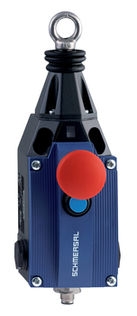
AS-Interface M12 connector, bottom, can be rotatedwith Emergency-Stop buttonMetal enclosureone-side operation / wire up to 75 m longRelease push buttonPosition indicatorRobust designTwisting of towing eye not possibleExternal watertight collarwire pull and breakage detectionIntegrated AS-InterfaceSuitable for AS-i Power24
- AS-Interface M12 connector, bottom, can be rotated
- with Emergency-Stop button
- Metal enclosure
- one-side operation / wire up to 75 m long
- Release push button
- Position indicator
- Robust design
- Twisting of towing eye not possible
- External watertight collar
- wire pull and breakage detection
- Integrated AS-Interface
- Suitable for AS-i Power24
Ordering data
| Note (Delivery capacity) | Not available! |
| Product type description | ZQ 900 ST-AS N |
| Article number (order number) | 101214840 |
| EAN (European Article Number) | 4030661404462 |
| eCl@ss number, version 12.0 | 27-37-12-01 |
| eCl@ss number, version 11.0 | 27-37-12-01 |
| eCl@ss number, version 9.0 | 27-37-12-01 |
| ETIM number, version 7.0 | EC002033 |
| ETIM number, version 6.0 | EC002033 |
Approvals - Standards
| cULus ASi-SaW |
General data
| Standards | EN 50295 EN ISO 13849-1 EN ISO 13850 EN IEC 60947-5-1 EN IEC 61508 |
| Housing material | Metal, zinc die-cast |
| Housing coating material | painted |
| Material of the housing cover | Plastic, glass-fibre reinforced thermoplastic, self-extinguishing |
| Length of the wire, maximum | 50 m |
| Reaction time, maximum | 100 ms |
| Gross weight | 1,365 g |
General data - Features
| Emergency-Stop button | Yes |
| Safety classification |
| Standards | EN IEC 61508 |
| Performance Level, up to | e |
| Category | 4 |
| PFH value | 1.40 x 10⁻⁸ /h |
| Note (PFH-value) | up to max. 5,000 switching cycles/year |
| Safety Integrity Level (SIL), suitable for applications in | 3 |
| Mission time | 20 Year(s) |
Mechanical data
| Mechanical life, minimum | 100,000 Operations |
| Actuating force, maximum | 200 N |
| Actuating travel | 400 mm |
Mechanical data - Connection technique
| Termination | Connector plug M12, 4-pole, (A-coding) |
Mechanical data - Dimensions
| Length of sensor | 97 mm |
| Width of sensor | 71.5 mm |
| Height of the Sensor, minimum | 220.3 mm |
| Height of the Sensor, maximum | 236.3 mm |
Ambient conditions
| Degree of protection | IP65 IP67 |
| Ambient temperature | -25 ... +60 °C |
| Storage and transport temperature | -25 ... +85 °C |
| Relative humidity, minimum | 30 % |
| Relative humidity, maximum | 95 % |
| Note (Relative humidity) | non-condensing non-icing |
| Resistance to vibrations | 10 … 150 Hz, amplitude 0.35 mm 10 … 150 Hz, with 5 g |
| Restistance to shock | 15 g / 11 ms |
Ambient conditions - Insulation values
| Rated insulation voltage Ui | 32 V |
| Rated impulse withstand voltage Uimp | 0.8 kV |
| Overvoltage category | III |
| Degree of pollution | 3 |
Electrical data
| Current consumption | 50 mA |
| Switching principle | Snap action |
| Maximum switching frequency | 3,600 /h |
Electrical data - AS Interface
| Rated operating voltage | 18 ... 31.6 VDC (Protection against polarity reversal) |
Electrical data - AS-Interface specification
| AS-i Version | V 3.0 |
| AS-i Profile | S-0.B.F.F |
| AS-i, IO-Code | 0x0 |
| AS-i, ID-Code | 0xB |
| AS-i, ID-Code1 | 0xF |
| AS-i, ID-Code2 | 0xF |
| AS-i Input, Channel 1 | Data bits DI 0 / DI 1 = dynamic code transmission |
| AS-i Input, Channel 2 | Data bits DI 2 / DI 3 = dynamic code transmission |
| AS-i Outputs, DO 0 … DO 3 | No Function |
| AS-i Parameter bits, P0 | Channel 2 switched |
| AS-i Parameter bits, P1 | No function |
| AS-i Parameter bits, P2 | No function |
| AS-i Parameter bits, P3 | No function |
| Note (AS-i Parameter bits) | Set the parameter outputs to ″1111″ (0xF) FID: periphery error |
| AS-i Input module address | 0 |
| Note (AS-i Input module address) | Preset to address 0, can be changed through AS-interface bus master or hand-held programming device |
Pin assignment
| PIN 1 | AS-Interface + |
| PIN 2 | n.c. |
| PIN 3 | AS-Interface - |
| PIN 4 | n.c. |
| PIN 5 | Functional earth connection |
Note
| Note (General) | Recommended cable lengths for pull-wire Emergency-Stop switches in relation to the range of ambient temperature. As the thimbles are subject to deformation in case of wire pull, the wire should be pulled several times after fitting. After that, the wire must be re-tensioned using the eyebolt or the tensioner. The addressing must take place via the M12 connector or the flat cable connection. At 5 m distance intermediate wire supports are required, see accessories |
All of our products ensure maximum reliability even in challenging working conditions and help your business operations run smoothly. The products we offer in industrial automation, energy management, cabling solutions, and many other areas adapt flexibly to the needs of different sectors.
Additionally, our products are manufactured using only high-quality materials and comply with international standards. Through the solutions we provide, we enable our customers to increase operational efficiency and optimize costs. Our company closely follows technological advancements and continuously offers innovative products to help our customers gain a competitive advantage.
On each of our product pages, you can find comprehensive information about technical details, areas of use, and product features. You can explore all the products you need to strengthen your industrial processes on our website and enjoy a seamless purchasing experience.
Similar Products


Can't find the product you're looking for?
LET US HELP YOU
Can't Find the Product You're Looking For? Let Us Know, and We'll Source It for You!
Are you searching for products not listed on our website or out of stock? Let us know your requirements, and our expert team will contact you as soon as possible to find the most suitable solution for you.