Eaton : ZB12-16
290168 ZB12-16
ZB12-16 /290168
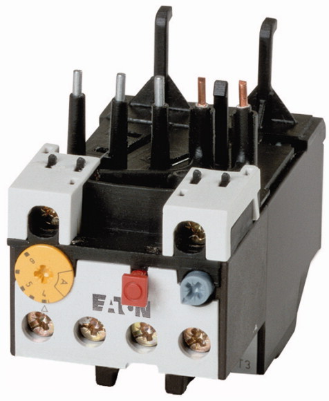
Overload relay, ZB12, Ir= 12 - 16 A, 1 N/O, 1 N/C, Direct mounting, IP20Overload relay, Product range: Overload relay ZB up to 150 A, Accessories: Overload relays, Frame size: ZB12, Phase-failure sensitivity: IEC/EN 60947, VDE 0660 Part 102, Description: Test/off button, Reset pushbutton manual/auto, Trip-free release, Mounting type: Direct mounting, Auxiliary contacts N/O = Normally open: 1 N/O, Auxiliary contacts N/C = Normally closed: 1 N/C, For use with: DILM7, DILM9, DILM12, DILM15,, DIULM7, DIULM9, DIULM12,, SDAINLM12,, SDAINLM16,, SDAINLM22, Standards: IEC/EN 60947, VDE 0660, UL, CSA, Degree of Protection: IP20
Overload relay, ZB12, Ir= 12 - 16 A, 1 N/O, 1 N/C, Direct mounting, IP20
Overload relay, Product range: Overload relay ZB up to 150 A, Accessories: Overload relays, Frame size: ZB12, Phase-failure sensitivity: IEC/EN 60947, VDE 0660 Part 102, Description: Test/off button, Reset pushbutton manual/auto, Trip-free release, Mounting type: Direct mounting, Auxiliary contacts N/O = Normally open: 1 N/O, Auxiliary contacts N/C = Normally closed: 1 N/C, For use with: DILM7, DILM9, DILM12, DILM15,, DIULM7, DIULM9, DIULM12,, SDAINLM12,, SDAINLM16,, SDAINLM22, Standards: IEC/EN 60947, VDE 0660, UL, CSA, Degree of Protection: IP20
| Product range | Overload relay ZB up to 150 A | |||||||
| Product range | Accessories | |||||||
| Accessories | Overload relays | |||||||
| Frame size | ZB12 | |||||||
| Phase-failure sensitivity | IEC/EN 60947, VDE 0660 Part 102 | |||||||
| Description | Test/off button Reset pushbutton manual/auto Trip-free release |
|||||||
| Mounting type | Direct mounting | |||||||
| Contact sequence | 12 - 16 A | |||||||
| N/O = Normally open | ||||||||
| N/C = Normally closed | ||||||||
| For use with | 1 N/O | |||||||
| Type “1” coordination |
1 N/C | |||||||
| Type “2” coordination |
DILM7, DILM9, DILM12, DILM15, DIULM7, DIULM9, DIULM12, SDAINLM12, SDAINLM16, SDAINLM22 |
|||||||
| Notes | ||||||||
| Notes | 50 A | |||||||
| Standards | 25 A | |||||||
| Climatic proofing | Overload release: tripping class 10 A short-circuit protective device: Observe the maximum permissible fuse of the contactor with direct device mounting. Suitable for protection of Ex e-motors.
PTB 10 ATEX 3010 Observe manual MN03407005Z-DE/EN. |
|||||||
| Ambient temperature |
|
|||||||
| Ambient temperature >Open |
||||||||
| Ambient temperature >Enclosed |
IEC/EN 60947, VDE 0660, UL, CSA | |||||||
| Temperature compensation | Damp heat, constant, to IEC 60068-2-78 Damp heat, cyclic, to IEC 60068-2-30 |
|||||||
| Weight | Operating range to IEC/EN 60947 PTB: -5 °C - +55 °C |
|||||||
| Mechanical shock resistance | -25 - +55 °C | |||||||
| Degree of Protection | - 25 - 40 °C | |||||||
| Protection against direct contact when actuated from front (EN 50274) | Continuous | |||||||
| Altitude | 0.145 kg | |||||||
| Rated impulse withstand voltage [Uimp] | 10 Sinusoidal Shock duration 10 ms g |
|||||||
| Overvoltage category/pollution degree | IP20 | |||||||
| Rated insulation voltage [Ui ] | Finger and back-of-hand proof | |||||||
| Rated operational voltage [Ue] | Max. 2000 m | |||||||
| Safe isolation to EN 61140 >Between auxiliary contacts and main contacts |
||||||||
| Safe isolation to EN 61140 >Between main circuits |
6000 V AC | |||||||
| Temperatur compensation residual error > 40 ºC | III/3 | |||||||
| Current heat loss (3 conductors) >Lower value of the setting range |
690 V | |||||||
| Current heat loss (3 conductors) >Maximum setting |
690 V AC | |||||||
| Terminal capacities >Solid |
440 V AC | |||||||
| Terminal capacities >Flexible with ferrule |
440 V AC | |||||||
| Terminal capacities >Solid or stranded |
≦ 0.25 %/K | |||||||
| Terminal screw | 3 W | |||||||
| Tightening torque | 5.4 W | |||||||
| Stripping length | 1 x (1 - 6) 2 x (1 - 6) mm2 |
|||||||
| Tools >Pozidriv screwdriver |
1 x (1 - 4) 2 x (1 - 4) mm2 |
|||||||
| Tools >Standard screwdriver |
18 - 8 AWG | |||||||
| Rated impulse withstand voltage [Uimp] | M4 | |||||||
| Overvoltage category/pollution degree | 1.8 Nm | |||||||
| Terminal capacities >Solid |
10 mm | |||||||
| Terminal capacities >Flexible with ferrule |
2 Size | |||||||
| Terminal capacities >Solid or stranded |
1 x 6 mm | |||||||
| Terminal screw | ||||||||
| Tightening torque | 4000 V | |||||||
| Stripping length | III/3 | |||||||
| Tools >Pozidriv screwdriver |
1 x (0.75 - 4) 2 x (0.75 - 4) mm2 |
|||||||
| Tools >Standard screwdriver |
1 x (0.75 - 2.5) 2 x (0.75 - 2.5) mm2 |
|||||||
| Rated insulation voltage [Ui ] | 2 x (18 - 14) AWG | |||||||
| Rated operational voltage [Ue ] | M3.5 | |||||||
| Safe isolation to EN 61140 >between the auxiliary contacts |
1.2 Nm | |||||||
| Conventional thermal current [Ith ] | 8 mm | |||||||
| Rated operational current [Ie
] >AC-15 >Make contact >120 V [Ie ] |
2 Size | |||||||
| Rated operational current [Ie
] >AC-15 >Make contact >220 V 230 V 240 V [Ie ] |
1 x 6 mm | |||||||
| Rated operational current [Ie
] >AC-15 >Make contact >380 V 400 V 415 V [Ie ] |
500 V AC | |||||||
| Rated operational current [Ie
] >AC-15 >Make contact >500 V [Ie ] |
500 V AC | |||||||
| Rated operational current [Ie
] >AC-15 >Break contact >120 V [Ie ] |
240 V AC | |||||||
| Rated operational current [Ie
] >AC-15 >Break contact >220 V 230 V 240 V [Ie ] |
6 A | |||||||
| Rated operational current [Ie
] >AC-15 >Break contact >380 V 400 V 415 V [Ie ] |
1.5 A | |||||||
| Rated operational current [Ie
] >AC-15 >Break contact >500 V [Ie ] |
1.5 A | |||||||
| Rated operational current [Ie
] >DC L/R ≦ 15 ms |
0.5 A | |||||||
| Rated operational current [Ie
] >DC L/R ≦ 15 ms >24 V [Ie ] |
0.5 A | |||||||
| Rated operational current [Ie
] >DC L/R ≦ 15 ms >60 V [Ie ] |
1.5 A | |||||||
| Rated operational current [Ie
] >DC L/R ≦ 15 ms >110 V [Ie ] |
1.5 A | |||||||
| Rated operational current [Ie
] >DC L/R ≦ 15 ms >220 V [Ie ] |
0.9 A | |||||||
| Short-circuit rating without welding >max. fuse |
0.8 A | |||||||
| Notes | Switch-on and switch-off conditions based on DC-13, time constant as specified. | |||||||
| Auxiliary contacts >Pilot Duty >AC operated |
0.9 A | |||||||
| Auxiliary contacts >Pilot Duty >DC operated |
0.75 A | |||||||
| Short Circuit Current Rating >600 V High Fault >SCCR (fuse) |
0.4 A | |||||||
| Short Circuit Current Rating >600 V High Fault >max. Fuse |
0.2 A | |||||||
| Rated operational current for specified heat dissipation [In] | 6 A gG/gL | |||||||
| Heat dissipation per pole, current-dependent [Pvid] | ||||||||
| Equipment heat dissipation, current-dependent [Pvid] | Ambient air temperature: Operating range to IEC/EN 60947, PTB: -5°C to +55°C Main circuits terminal capacity solid and flexible conductors with ferrules: When using 2 conductors use equal cross-sections. |
|||||||
| Static heat dissipation, non-current-dependent [Pvs] | ||||||||
| Heat dissipation capacity [Pdiss] | B300 at opposite polarity B600 at same polarity |
|||||||
| Operating ambient temperature min. | R300 | |||||||
| Operating ambient temperature max. | 100 kA | |||||||
| 10.2 Strength of materials and parts >10.2.2 Corrosion resistance |
30 Class J/CC A | |||||||
| 10.2 Strength of materials and parts >10.2.3.1 Verification of thermal stability of enclosures |
||||||||
| 10.2 Strength of materials and parts >10.2.3.2 Verification of resistance of insulating materials to normal heat |
16 A | |||||||
| 10.2 Strength of materials and parts >10.2.3.3 Verification of resistance of insulating materials to abnormal heat and fire due to internal electric effects |
1.8 W | |||||||
| 10.2 Strength of materials and parts >10.2.4 Resistance to ultra-violet (UV) radiation |
5.4 W | |||||||
| 10.2 Strength of materials and parts >10.2.5 Lifting |
0 W | |||||||
| 10.2 Strength of materials and parts >10.2.6 Mechanical impact |
0 W | |||||||
| 10.2 Strength of materials and parts >10.2.7 Inscriptions |
-25 °C | |||||||
| 10.3 Degree of protection of ASSEMBLIES | +55 °C | |||||||
| 10.4 Clearances and creepage distances | ||||||||
| 10.5 Protection against electric shock | Meets the product standard´s requirements. | |||||||
| 10.6 Incorporation of switching devices and components | Meets the product standard´s requirements. | |||||||
| 10.7 Internal electrical circuits and connections | Meets the product standard´s requirements. | |||||||
| 10.8 Connections for external conductors | Meets the product standard´s requirements. | |||||||
| 10.9 Insulation properties >10.9.2 Power-frequency electric strength |
Meets the product standard´s requirements. | |||||||
| 10.9 Insulation properties >10.9.3 Impulse withstand voltage |
Does not apply, since the entire switchgear needs to be evaluated. | |||||||
| 10.9 Insulation properties >10.9.4 Testing of enclosures made of insulating material |
Does not apply, since the entire switchgear needs to be evaluated. | |||||||
| 10.10 Temperature rise | Meets the product standard´s requirements. | |||||||
| 10.11 Short-circuit rating | Does not apply, since the entire switchgear needs to be evaluated. | |||||||
| 10.12 Electromagnetic compatibility | Meets the product standard´s requirements. | |||||||
| 10.13 Mechanical function | Does not apply, since the entire switchgear needs to be evaluated. | |||||||
| Adjustable current range | Does not apply, since the entire switchgear needs to be evaluated. | |||||||
| Max. rated operation voltage Ue | Is the panel builder´s responsibility. | |||||||
| Mounting method | Is the panel builder´s responsibility. | |||||||
| Type of electrical connection of main circuit | Is the panel builder´s responsibility. | |||||||
| Number of auxiliary contacts as normally closed contact | Is the panel builder´s responsibility. | |||||||
| Number of auxiliary contacts as normally open contact | Is the panel builder´s responsibility. | |||||||
| Number of auxiliary contacts as change-over contact | The panel builder is responsible for the temperature rise calculation. Eaton will provide heat dissipation data for the devices. | |||||||
| Release class | Is the panel builder´s responsibility. The specifications for the switchgear must be observed. | |||||||
| Reset function input | Is the panel builder´s responsibility. The specifications for the switchgear must be observed. | |||||||
| Reset function automatic | The device meets the requirements, provided the information in the instruction leaflet (IL) is observed. | |||||||
| Reset function push-button | ||||||||
| Product Standards | ||||||||
| UL File No. | 12 - 16 A | |||||||
| UL Category Control No. | 690 V | |||||||
| CSA File No. | Direct attachment | |||||||
| CSA Class No. | Screw connection | |||||||
| North America Certification | 1 | |||||||
| Specially designed for North America | 1 | |||||||
| Suitable for | 0 | |||||||
| Max. Voltage Rating | CLASS 10 | |||||||
| Degree of Protection | No | |||||||
| Characteristic curve | Yes |
All of our products ensure maximum reliability even in challenging working conditions and help your business operations run smoothly. The products we offer in industrial automation, energy management, cabling solutions, and many other areas adapt flexibly to the needs of different sectors.
Additionally, our products are manufactured using only high-quality materials and comply with international standards. Through the solutions we provide, we enable our customers to increase operational efficiency and optimize costs. Our company closely follows technological advancements and continuously offers innovative products to help our customers gain a competitive advantage.
On each of our product pages, you can find comprehensive information about technical details, areas of use, and product features. You can explore all the products you need to strengthen your industrial processes on our website and enjoy a seamless purchasing experience.
Similar Products


Can't find the product you're looking for?
LET US HELP YOU
Can't Find the Product You're Looking For? Let Us Know, and We'll Source It for You!
Are you searching for products not listed on our website or out of stock? Let us know your requirements, and our expert team will contact you as soon as possible to find the most suitable solution for you.