Eaton : NZMH4-ME875-S1
290384 NZMH4-ME875-S1
NZMH4-ME875-S1 /290384
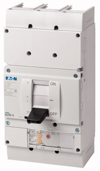
Circuit-breaker, 3p, 875A 1000VSeries NZM..-ME circuit-breakers cover all application cases with just four compact sizes and are suitable for the IEC market. Modular function groups always make mounting flexible. With electronic release for motor protection with phase failure sensitivity. Notes: r.m.s. value measurement and thermal memory, adjustable time delay setting to overcome current peaks tr:2-20 at 6xIr as well as infinity (without overload release), NZM...S1 terminal type: NZM...XKSA cover required, NZM4...S1 terminal type: Insulated busbar connection (NZM4-XKS screw connection)
Circuit-breaker, 3p, 875A 1000V
Series NZM..-ME circuit-breakers cover all application cases with just four compact sizes and are suitable for the IEC market. Modular function groups always make mounting flexible. With electronic release for motor protection with phase failure sensitivity. Notes: r.m.s. value measurement and thermal memory, adjustable time delay setting to overcome current peaks tr:2-20 at 6xIr as well as infinity (without overload release), NZM...S1 terminal type: NZM...XKSA cover required, NZM4...S1 terminal type: Insulated busbar connection (NZM4-XKS screw connection)
| Product range | Circuit-breaker |
| Protective function | Motor protection |
| Standard/Approval | |
| Installation type | IEC |
| Release system | Fixed |
| Construction size | Electronic release |
| Description | NZM4 |
| Number of poles | Phase-failure sensitivity IEC/EN 60947-4-1, IEC/EN 60947-2 R.m.s. value measurement and “thermal memory” adjustable time delay setting to overcome current peaks tr: 2 – 20 s at 6 x Ir also infinity (without overload releases) NZM...S1 terminal type: NZM...XKSA cover required NZM4...S1 terminal type: Insulated busbar connection (NZM4-XKS screw connection) |
| Standard equipment | 3 pole |
| Rated current = rated uninterrupted current [In = Iu] | Screw connection |
| 1000 V 50/60 Hz [Icu] | 875 A |
| Overload trip 438 - 875 A
Short-circuit releases >Non-delayed |
20 kA |
| Rated surge voltage invariability [Uimp
] >Main contacts |
438 - 875 A |
| Rated surge voltage invariability [Uimp
] >Auxiliary contacts |
2 - 14 |
| Rated operational voltage [Ue] | 8000 V |
| Rated current = rated uninterrupted current [In = Iu] | 6000 V |
| Overvoltage category/pollution degree | 1000 V AC |
| Rated insulation voltage [Ui ] | 875 A |
| Utilization category | III/3 |
| Ambient temperature >Ambient temperature, storage |
1000 V |
| Ambient temperature >Operation |
B |
| 240 V 50/60 Hz [Icm ] | - 40 - + 70 °C |
| 400/415 V 50/60 Hz [Icm ] | -25 - +70 °C |
| 440 V 50/60 Hz [Icm ] | 275 kA |
| 525 V 50/60 Hz [Icm ] | 187 kA |
| 690 V 50/60 H [Ic] | 187 kA |
| 1000 V 50/60 Hz [Icm] | 143 kA |
| Icu to IEC/EN 60947 test cycle O-t-CO [Icu] >240 V 50/60 Hz [Icu ] |
100 kA |
| Icu to IEC/EN 60947 test cycle O-t-CO [Icu] >400/415 V 50 Hz [Icu ] |
40 kA |
| Icu to IEC/EN 60947 test cycle O-t-CO [Icu] >440 V 50/60 Hz [Icu ] |
125 kA |
| Icu to IEC/EN 60947 test cycle O-t-CO [Icu] >525 V 50/60 Hz [Icu ] |
85 kA |
| Icu to IEC/EN 60947 test cycle O-t-CO [Icu] >690 V 50/60 Hz [Icu ] |
85 kA |
| Icu to IEC/EN 60947 test cycle O-t-CO [Icu] >1000 V 50/60 Hz [Icu] |
65 kA |
| Ics to IEC/EN 60947 test cycle O-t-CO-t-CO [Ics] >230 V 50/60 Hz [Ics ] |
50 kA |
| Ics to IEC/EN 60947 test cycle O-t-CO-t-CO [Ics] >400/415 V 50/60 Hz [Ics ] |
20 kA |
| Ics to IEC/EN 60947 test cycle O-t-CO-t-CO [Ics] >440 V 50/60 Hz [Ics ] |
63 kA |
| Ics to IEC/EN 60947 test cycle O-t-CO-t-CO [Ics] >525 V 50/60 Hz [Ics ] |
50 kA |
| Ics to IEC/EN 60947 test cycle O-t-CO-t-CO [Ics] >690 V 50/60 Hz [Ics] |
50 kA |
| Ics to IEC/EN 60947 test cycle O-t-CO-t-CO [Ics] >1000 V AC [Ics] |
50 kA |
| t = 0.3 s [Icw ] | 37 kA |
| t = 1 s [Icw ] | 15 kA |
| Lifespan, mechanical [Operations] | 19.2 kA |
| Max. operating frequency | 19.2 kA |
| 1000 V 50/60 Hz [Operations] | 10000 |
| Standard equipment | 60 Ops/h |
| Round copper conductor >Tunnel terminal >Stranded >4-hole |
Lifespan, mechanical: of which max. 50 % trip by shunt/undervoltage release |
| Round copper conductor >Bolt terminal and rear-side connection >Module plate >Single hole [min.] |
500 |
| Round copper conductor >Bolt terminal and rear-side connection >Module plate >Single hole [max.] |
Screw connection |
| Round copper conductor >Bolt terminal and rear-side connection >Module plate >Double hole [min.] |
4 x (50 - 240) mm2 |
| Round copper conductor >Bolt terminal and rear-side connection >Module plate >Double hole [max.] |
1 x (185 - 240) mm2 |
| Round copper conductor >Bolt terminal and rear-side connection >Connection width extension >Connection width extension |
2 x (70 - 185) mm2 |
| Al conductors, Cu cable >Tunnel terminal >Stranded >4-hole |
4 x 50 mm2 |
| Cu strip (number of segments x width x segment thickness) >Flat conductor terminal [min.] |
4 x (35 - 185) mm2 |
| Cu strip (number of segments x width x segment thickness) >Flat conductor terminal [max.] |
2 x 240 6 x (70 - 240) mm2 |
| Cu strip (number of segments x width x segment thickness) >Module plate >Single hole |
4 x (50 - 240) mm2 |
| Cu strip (number of segments x width x segment thickness) >Bolt terminal and rear-side connection >Flat copper strip, with holes [min.] |
6 x 16 x 0.8 mm |
| Cu strip (number of segments x width x segment thickness) >Bolt terminal and rear-side connection >Flat copper strip, with holes [max.] |
(2 x) 10 x 32 x 1.0 mm |
| Cu strip (number of segments x width x segment thickness) >Bolt terminal and rear-side connection >Connection width extension |
(2 x) 10 x 50 x 1.0 mm |
| Copper busbar (width x thickness) [mm] >Bolt terminal and rear-side connection >Screw connection |
(2 x) 10 x 50 x 1.0 mm |
| Copper busbar (width x thickness) [mm] >Bolt terminal and rear-side connection >Direct on the switch [min.] |
(2 x) 10 x 50 x 1.0 mm |
| Copper busbar (width x thickness) [mm] >Bolt terminal and rear-side connection >Direct on the switch [max.] |
(2 x) 10 x 80 x 1.0 mm |
| Copper busbar (width x thickness) [mm] >Bolt terminal and rear-side connection >Module plate >Single hole [min.] |
M10 |
| Copper busbar (width x thickness) [mm] >Bolt terminal and rear-side connection >Module plate >Single hole [max.] |
25 x 5 mm |
| Copper busbar (width x thickness) [mm] >Bolt terminal and rear-side connection >Module plate >Double hole |
2 x (50 x 10) 2 x (80 x 10) mm |
| Copper busbar (width x thickness) [mm] >Bolt terminal and rear-side connection >Connection width extension >Connection width extension [min.] |
25 x 5 mm |
| Copper busbar (width x thickness) [mm] >Bolt terminal and rear-side connection >Connection width extension >Connection width extension [max.] |
2 x (50 x 10) mm |
| Control cables | 2 x (50 x 10) mm |
| Rated operational current for specified heat dissipation [In] | 60 x 10 mm |
| Equipment heat dissipation, current-dependent [Pvid] | 2 x (80 x 10) mm |
| Operating ambient temperature min. | 1 x (0.75 - 2.5) 2 x (0.75 - 1.5) mm2 |
| Operating ambient temperature max. | 875 A |
| 10.2 Strength of materials and parts >10.2.2 Corrosion resistance |
84.98 W |
| 10.2 Strength of materials and parts >10.2.3.1 Verification of thermal stability of enclosures |
-25 °C |
| 10.2 Strength of materials and parts >10.2.3.2 Verification of resistance of insulating materials to normal heat |
+70 °C |
| 10.2 Strength of materials and parts >10.2.3.3 Verification of resistance of insulating materials to abnormal heat and fire due to internal electric effects |
Meets the product standard´s requirements. |
| 10.2 Strength of materials and parts >10.2.4 Resistance to ultra-violet (UV) radiation |
Meets the product standard´s requirements. |
| 10.2 Strength of materials and parts >10.2.5 Lifting |
Meets the product standard´s requirements. |
| 10.2 Strength of materials and parts >10.2.6 Mechanical impact |
Meets the product standard´s requirements. |
| 10.2 Strength of materials and parts >10.2.7 Inscriptions |
Meets the product standard´s requirements. |
| 10.3 Degree of protection of ASSEMBLIES | Does not apply, since the entire switchgear needs to be evaluated. |
| 10.4 Clearances and creepage distances | Does not apply, since the entire switchgear needs to be evaluated. |
| 10.5 Protection against electric shock | Meets the product standard´s requirements. |
| 10.6 Incorporation of switching devices and components | Does not apply, since the entire switchgear needs to be evaluated. |
| 10.7 Internal electrical circuits and connections | Meets the product standard´s requirements. |
| 10.8 Connections for external conductors | Does not apply, since the entire switchgear needs to be evaluated. |
| 10.9 Insulation properties >10.9.2 Power-frequency electric strength |
Does not apply, since the entire switchgear needs to be evaluated. |
| 10.9 Insulation properties >10.9.3 Impulse withstand voltage |
Is the panel builder´s responsibility. |
| 10.9 Insulation properties >10.9.4 Testing of enclosures made of insulating material |
Is the panel builder´s responsibility. |
| 10.10 Temperature rise | Is the panel builder´s responsibility. |
| 10.11 Short-circuit rating | Is the panel builder´s responsibility. |
| 10.12 Electromagnetic compatibility | Is the panel builder´s responsibility. |
| 10.13 Mechanical function | The panel builder is responsible for the temperature rise calculation. Eaton will provide heat dissipation data for the devices. |
| Overload release current setting | Is the panel builder´s responsibility. The specifications for the switchgear must be observed. |
| Adjustment range undelayed short-circuit release | Is the panel builder´s responsibility. The specifications for the switchgear must be observed. |
| With thermal protection | The device meets the requirements, provided the information in the instruction leaflet (IL) is observed. |
| Phase failure sensitive | 438 - 875 A |
| Switch off technique | 875 - 12250 A |
| Rated operating voltage | Yes |
| Rated permanent current Iu | Yes |
| Rated operation power at AC-3, 230 V | Electronic |
| Rated operation power at AC-3, 400 V | 1000 - 1000 V |
| Type of electrical connection of main circuit | 875 A |
| Type of control element | 250 kW |
| Device construction | 500 kW |
| With integrated auxiliary switch | Screw connection |
| With integrated under voltage release | Rocker lever |
| Number of poles | Built-in device fixed built-in technique |
| Rated short-circuit breaking capacity lcu at 400 V, AC | No |
| Degree of protection (IP) | No |
| Height | 3 |
| Width | 150 kA |
| Depth | IP20 |
| Characteristic curve | 207 mm |
All of our products ensure maximum reliability even in challenging working conditions and help your business operations run smoothly. The products we offer in industrial automation, energy management, cabling solutions, and many other areas adapt flexibly to the needs of different sectors.
Additionally, our products are manufactured using only high-quality materials and comply with international standards. Through the solutions we provide, we enable our customers to increase operational efficiency and optimize costs. Our company closely follows technological advancements and continuously offers innovative products to help our customers gain a competitive advantage.
On each of our product pages, you can find comprehensive information about technical details, areas of use, and product features. You can explore all the products you need to strengthen your industrial processes on our website and enjoy a seamless purchasing experience.
Similar Products


Can't find the product you're looking for?
LET US HELP YOU
Can't Find the Product You're Looking For? Let Us Know, and We'll Source It for You!
Are you searching for products not listed on our website or out of stock? Let us know your requirements, and our expert team will contact you as soon as possible to find the most suitable solution for you.