Eaton : NZMH3-AE400-S1
119362 NZMH3-AE400-S1
NZMH3-AE400-S1 /119362
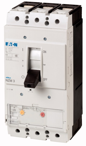
Circuit-breaker, 3p, 400A, 1000 VCircuit-breaker NZM3, 3 pole, Switching capacity 1000 V 50/60 Hz( Ics): 15 kA, Rated current = rated uninterrupted current( In = Iu): 400 A, Installation type: Fixed, Screw connection, Standard/Approval: IEC, Protective function: System and cable protection
Circuit-breaker, 3p, 400A, 1000 V
Circuit-breaker NZM3, 3 pole, Switching capacity 1000 V 50/60 Hz( Ics): 15 kA, Rated current = rated uninterrupted current( In = Iu): 400 A, Installation type: Fixed, Screw connection, Standard/Approval: IEC, Protective function: System and cable protection
| Product range | Circuit-breaker |
| Protective function | System and cable protection |
| Standard/Approval | IEC |
| Installation type | Fixed |
| Release system | Electronic release |
| Construction size | NZM3 |
| Description | R.m.s. value measurement and “thermal memory” NZM...S1 terminal type: NZM...XKSA cover required |
| Number of poles | 3 pole |
| Standard equipment | Screw connection |
| Rated current = rated uninterrupted current [In = Iu] | 400 A |
| 1000 V 50/60 Hz [Icu] | 15 kA |
| Overload trip 200 - 400 A
Short-circuit releases >Non-delayed |
200 - 400 A |
| Rated surge voltage invariability [Uimp
] >Main contacts |
2 - 11 |
| Rated surge voltage invariability [Uimp
] >Auxiliary contacts |
8000 V |
| Rated operational voltage [Ue] | 6000 V |
| Rated current = rated uninterrupted current [In = Iu] | 1000 V AC |
| Overvoltage category/pollution degree | 400 A |
| Rated insulation voltage [Ui ] | III/3 |
| Utilization category | 1000 V |
| Ambient temperature >Ambient temperature, storage |
A |
| Ambient temperature >Operation |
- 40 - + 70 °C |
| 240 V 50/60 Hz [Icm ] | -25 - +70 °C |
| 400/415 V 50/60 Hz [Icm ] | 330 kA |
| 440 V 50/60 Hz [Icm ] | 330 kA |
| 525 V 50/60 Hz [Icm ] | 286 kA |
| 690 V 50/60 H [Ic] | 143 kA |
| 1000 V 50/60 Hz [Icm] | 74 kA |
| Icu to IEC/EN 60947 test cycle O-t-CO [Icu] >240 V 50/60 Hz [Icu ] |
17 kA |
| Icu to IEC/EN 60947 test cycle O-t-CO [Icu] >400/415 V 50 Hz [Icu ] |
150 kA |
| Icu to IEC/EN 60947 test cycle O-t-CO [Icu] >440 V 50/60 Hz [Icu ] |
150 kA |
| Icu to IEC/EN 60947 test cycle O-t-CO [Icu] >525 V 50/60 Hz [Icu ] |
130 kA |
| Icu to IEC/EN 60947 test cycle O-t-CO [Icu] >690 V 50/60 Hz [Icu ] |
65 kA |
| Icu to IEC/EN 60947 test cycle O-t-CO [Icu] >1000 V 50/60 Hz [Icu] |
35 kA |
| Ics to IEC/EN 60947 test cycle O-t-CO-t-CO [Ics] >230 V 50/60 Hz [Ics ] |
15 kA |
| Ics to IEC/EN 60947 test cycle O-t-CO-t-CO [Ics] >400/415 V 50/60 Hz [Ics ] |
150 kA |
| Ics to IEC/EN 60947 test cycle O-t-CO-t-CO [Ics] >440 V 50/60 Hz [Ics ] |
150 kA |
| Ics to IEC/EN 60947 test cycle O-t-CO-t-CO [Ics] >525 V 50/60 Hz [Ics ] |
130 kA |
| Ics to IEC/EN 60947 test cycle O-t-CO-t-CO [Ics] >690 V 50/60 Hz [Ics] |
33 kA |
| Ics to IEC/EN 60947 test cycle O-t-CO-t-CO [Ics] >1000 V AC [Ics] |
9 kA |
| t = 0.3 s [Icw ] | 10 kA |
| t = 1 s [Icw ] | 3.3 kA |
| Lifespan, mechanical [Operations] | 3.3 kA |
| Max. operating frequency | 15000 |
| 1000 V 50/60 Hz [Operations] | 60 Ops/h |
| Standard equipment | Lifespan, mechanical: of which max. 50 % trip by shunt/undervoltage release |
| Round copper conductor >Box terminal >Solid |
1000 |
| Round copper conductor >Box terminal >Stranded |
Screw connection |
| Round copper conductor >Tunnel terminal >Stranded >Stranded |
2 x 16 mm2 |
| Round copper conductor >Tunnel terminal >Stranded >Double hole |
1 x (35 - 240) 2 x (25 - 120) mm2 |
| Round copper conductor >Bolt terminal and rear-side connection >Direct on the switch >Solid |
1 x (25 - 185) mm2 |
| Round copper conductor >Bolt terminal and rear-side connection >Direct on the switch >Stranded |
1 x (50 - 240) 2 x (50 - 240) mm2 |
| Al conductors, Cu cable >Tunnel terminal >Solid |
1 x 16 2 x (10 - 16 mm2 |
| Al conductors, Cu cable >Tunnel terminal >Stranded >Stranded |
1 x (25 - 120) 2 x (25 - 120) mm2 |
| Al conductors, Cu cable >Tunnel terminal >Stranded |
1 x 16 mm2 |
| Al conductors, Cu cable >Tunnel terminal >Stranded >Double hole |
1 x (25 - 185) 2) mm2 |
| Cu strip (number of segments x width x segment thickness) >Box terminal [min.] |
2) Up to 240 mm² can be connected depending on the cable manufacturer. |
| Cu strip (number of segments x width x segment thickness) >Box terminal [max.] |
1 x (50 - 240) 2 x (50 - 240) mm2 |
| Cu strip (number of segments x width x segment thickness) >Bolt terminal and rear-side connection >Flat copper strip, with holes [min.] |
6 x 16 x 0.8 mm |
| Cu strip (number of segments x width x segment thickness) >Bolt terminal and rear-side connection >Flat copper strip, with holes [max.] |
10 x 24 x 1.0 + 5 x 24 x 1.0 (2 x) 8 x 24 x 1.0 mm |
| Cu strip (number of segments x width x segment thickness) >Bolt terminal and rear-side connection >Connection width extension |
6 x 16 x 0.8 mm |
| Copper busbar (width x thickness) [mm] >Bolt terminal and rear-side connection >Screw connection |
10 x 32 x 1.0 + 5 x 32 x 1.0 mm |
| Copper busbar (width x thickness) [mm] >Bolt terminal and rear-side connection >Direct on the switch [min.] |
(2 x) 10 x 50 x 1.0 mm |
| Copper busbar (width x thickness) [mm] >Bolt terminal and rear-side connection >Direct on the switch [max.] |
M10 |
| Copper busbar (width x thickness) [mm] >Bolt terminal and rear-side connection >Connection width extension >Connection width extension [max.] |
20 x 5 mm |
| Control cables | 30 x 10 + 30 x 5 mm |
| Rated operational current for specified heat dissipation [In] | 2 x (10 x 50) mm |
| Equipment heat dissipation, current-dependent [Pvid] | 1 x (0.75 - 2.5) 2 x (0.75 - 1.5) mm2 |
| Operating ambient temperature min. | 400 A |
| Operating ambient temperature max. | 48 W |
| 10.2 Strength of materials and parts >10.2.2 Corrosion resistance |
-25 °C |
| 10.2 Strength of materials and parts >10.2.3.1 Verification of thermal stability of enclosures |
+70 °C |
| 10.2 Strength of materials and parts >10.2.3.2 Verification of resistance of insulating materials to normal heat |
Meets the product standard´s requirements. |
| 10.2 Strength of materials and parts >10.2.3.3 Verification of resistance of insulating materials to abnormal heat and fire due to internal electric effects |
Meets the product standard´s requirements. |
| 10.2 Strength of materials and parts >10.2.4 Resistance to ultra-violet (UV) radiation |
Meets the product standard´s requirements. |
| 10.2 Strength of materials and parts >10.2.5 Lifting |
Meets the product standard´s requirements. |
| 10.2 Strength of materials and parts >10.2.6 Mechanical impact |
Meets the product standard´s requirements. |
| 10.2 Strength of materials and parts >10.2.7 Inscriptions |
Does not apply, since the entire switchgear needs to be evaluated. |
| 10.3 Degree of protection of ASSEMBLIES | Does not apply, since the entire switchgear needs to be evaluated. |
| 10.4 Clearances and creepage distances | Meets the product standard´s requirements. |
| 10.5 Protection against electric shock | Does not apply, since the entire switchgear needs to be evaluated. |
| 10.6 Incorporation of switching devices and components | Meets the product standard´s requirements. |
| 10.7 Internal electrical circuits and connections | Does not apply, since the entire switchgear needs to be evaluated. |
| 10.8 Connections for external conductors | Does not apply, since the entire switchgear needs to be evaluated. |
| 10.9 Insulation properties >10.9.2 Power-frequency electric strength |
Is the panel builder´s responsibility. |
| 10.9 Insulation properties >10.9.3 Impulse withstand voltage |
Is the panel builder´s responsibility. |
| 10.9 Insulation properties >10.9.4 Testing of enclosures made of insulating material |
Is the panel builder´s responsibility. |
| 10.10 Temperature rise | Is the panel builder´s responsibility. |
| 10.11 Short-circuit rating | Is the panel builder´s responsibility. |
| 10.12 Electromagnetic compatibility | The panel builder is responsible for the temperature rise calculation. Eaton will provide heat dissipation data for the devices. |
| 10.13 Mechanical function | Is the panel builder´s responsibility. The specifications for the switchgear must be observed. |
| Rated permanent current Iu | Is the panel builder´s responsibility. The specifications for the switchgear must be observed. |
| Rated voltage | The device meets the requirements, provided the information in the instruction leaflet (IL) is observed. |
| Rated short-circuit breaking capacity lcu at 400 V, 50 Hz | 400 A |
| Overload release current setting | 1000 - 1000 V |
| Adjustment range short-term delayed short-circuit release | 150 kA |
| Adjustment range undelayed short-circuit release | 200 - 400 A |
| Integrated earth fault protection | 0 - 0 A |
| Type of electrical connection of main circuit | 800 - 4400 A |
| Device construction | No |
| Suitable for DIN rail (top hat rail) mounting | Screw connection |
| DIN rail (top hat rail) mounting optional | Built-in device fixed built-in technique |
| Number of auxiliary contacts as normally closed contact | No |
| Number of auxiliary contacts as normally open contact | No |
| Number of auxiliary contacts as change-over contact | 0 |
| With switched-off indicator | 0 |
| With under voltage release | 0 |
| Number of poles | No |
| Position of connection for main current circuit | No |
| Type of control element | 3 |
| Complete device with protection unit | Front side |
| Motor drive integrated | Rocker lever |
| Motor drive optional | Yes |
| Degree of protection (IP) | No |
| Characteristic curve | Yes |
| Characteristic curve | IP20 |
| Characteristic curve |
All of our products ensure maximum reliability even in challenging working conditions and help your business operations run smoothly. The products we offer in industrial automation, energy management, cabling solutions, and many other areas adapt flexibly to the needs of different sectors.
Additionally, our products are manufactured using only high-quality materials and comply with international standards. Through the solutions we provide, we enable our customers to increase operational efficiency and optimize costs. Our company closely follows technological advancements and continuously offers innovative products to help our customers gain a competitive advantage.
On each of our product pages, you can find comprehensive information about technical details, areas of use, and product features. You can explore all the products you need to strengthen your industrial processes on our website and enjoy a seamless purchasing experience.
Similar Products


Can't find the product you're looking for?
LET US HELP YOU
Can't Find the Product You're Looking For? Let Us Know, and We'll Source It for You!
Are you searching for products not listed on our website or out of stock? Let us know your requirements, and our expert team will contact you as soon as possible to find the most suitable solution for you.