Eaton : EMS2-DO-T-3-SWD
192383 EMS2-DO-T-3-SWD
EMS2-DO-T-3-SWD /192383
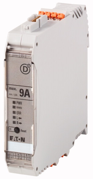
DOL starter, 24 V DC, 0,18 - 3 A, Push in terminals, SmartWire-DT slaveDOL starter, Product range: Electronic motor starter, SmartWire-DT slave, Function: For connecting to SmartWire-DT for expanded diagnostics, Description: DOL starting, Motor protection, Circuit design: safety output stage with bypass, three-phase disconnect., Motor current additionally adjustable via SmartWire-DT., Motor ratings Max. rating for three-phase motors, 50 - 60 Hz AC-53a 380 V 400 V 415 V: P= 0.06 - 0.75 kW, Setting range of overload releases: Ir= 0,18 - 3 A_x, Actuating voltage: 24 V DC, Connection technique: Push in terminals, Connection to SmartWire-DT: yes, Mounting position: Vertical, Motor feeder at bottom, Standards: IEC/EN 60947-4-2, UL508
DOL starter, 24 V DC, 0,18 - 3 A, Push in terminals, SmartWire-DT slave
DOL starter, Product range: Electronic motor starter, SmartWire-DT slave, Function: For connecting to SmartWire-DT for expanded diagnostics, Description: DOL starting, Motor protection, Circuit design: safety output stage with bypass, three-phase disconnect., Motor current additionally adjustable via SmartWire-DT., Motor ratings Max. rating for three-phase motors, 50 - 60 Hz AC-53a 380 V 400 V 415 V: P= 0.06 - 0.75 kW, Setting range of overload releases: Ir= 0,18 - 3 A_x, Actuating voltage: 24 V DC, Connection technique: Push in terminals, Connection to SmartWire-DT: yes, Mounting position: Vertical, Motor feeder at bottom, Standards: IEC/EN 60947-4-2, UL508
| Product range | Electronic motor starter |
| Product range | SmartWire-DT slave |
| Subrange | SmartWire-DT electronic motor starters |
| Basic function | DOL starters (complete devices) |
| Function | For connecting to SmartWire-DT for expanded diagnostics |
| Description | DOL starting Motor protection Circuit design: safety output stage with bypass, three-phase disconnect. Motor current additionally adjustable via SmartWire-DT. |
| Messages | Operational readiness Operating direction feedback Motor current in % Motor current in A Thermal motor image in % Overload prewarning Trip indications (overload, phase failure, etc.) Set short-circuit release value Device Type |
| Commands | Operating the motor starter Manual reset Automatic reset |
| Max. rating for three-phase motors, 50 - 60 Hz >AC-53a >380 V 400 V 415 V [P] |
|
| Setting range of overload releases |
0.06 - 1.1 kW |
| Actuating voltage | 0,18 - 3 A_x |
| Connection technique | 24 V DC |
| Connection to SmartWire-DT | Push in terminals |
| Standards | yes |
| Ambient temperature >Storage >Min. ambient temperature, storage |
|
| Ambient temperature >Storage >Ambient temperature, storage max. |
IEC/EN 60947-4-2 UL508 |
| Ambient temperature >Open >Operating ambient temperature min. |
- 40 °C |
| Ambient temperature >Open >Operating ambient temperature max. |
+ 80 °C |
| Weight | -5 °C |
| Mounting | +55 °C |
| Protection type (IEC/EN 60529, EN50178, VBG 4) | 0.22 kg |
| Mounting position | Top-hat rail IEC/EN 60715, 35 mm |
| Terminal capacity >Push-in terminals |
IP20 |
| Terminal capacity >Push-in terminals |
Vertical Motor feeder at bottom |
| Rated operational voltage [Ue] | 0.2 - 2.5 mm2 |
| Operational voltage range >Operating voltage range min. |
24 - 14 AWG |
| Operational voltage range >Operating voltage range max. |
|
| Rated operational current >AC-51 [Ie] |
500 V AC |
| Rated operational current >AC-53a [Ie] |
42 V |
| Rated operational current | 550 V |
| Rated operational current >Setting range of overload releases |
3 A |
| Release class | 3 A |
| Heat dissipation [PV] | AC-53a: Please note possible derating. |
| Rated control voltage [Us ] | 0,18 - 3 A_x |
| Control voltage range | 10 CLASS |
| Residual ripple on the input voltage | 0.1 - 2.5 W |
| Rated control current [Is] | |
| Current draw inrush | 24 V DC |
| Actuating circuit (ON, L, R) >Rated actuation voltage [Uc ] |
19,2 - 30 V DC V |
| Actuating circuit (ON, L, R) >Switching level "Low" |
≦ 5 % |
| Actuating circuit (ON, L, R) >Switching level "confirm Off" |
60 mA |
| Actuating circuit (ON, L, R) >Switching level "High" |
120 mA |
| Actuating circuit (ON, L, R) >Rated actuating current [Ic] |
24 V |
| Radio interference suppression | -3 - +9.6 V DC V |
| Rated operational current for specified heat dissipation [In] | < 5 V DC V |
| Heat dissipation per pole, current-dependent [Pvid] | 19.2 - 30 V DC V |
| Equipment heat dissipation, current-dependent [Pvid] | 7 mA |
| Static heat dissipation, non-current-dependent [Pvs] | |
| Heat dissipation capacity [Pdiss] | EN 55011 EN 61000-6-3, Class A (emitted interference, radiated) |
| Operating ambient temperature min. | |
| Operating ambient temperature max. | 3 A |
| 10.2 Strength of materials and parts >10.2.2 Corrosion resistance |
0 W |
| 10.2 Strength of materials and parts >10.2.3.1 Verification of thermal stability of enclosures |
2.5 W |
| 10.2 Strength of materials and parts >10.2.3.2 Verification of resistance of insulating materials to normal heat |
2 W |
| 10.2 Strength of materials and parts >10.2.3.3 Verification of resistance of insulating materials to abnormal heat and fire due to internal electric effects |
0 W |
| 10.2 Strength of materials and parts >10.2.4 Resistance to ultra-violet (UV) radiation |
-5 °C |
| 10.2 Strength of materials and parts >10.2.5 Lifting |
+55 °C |
| 10.2 Strength of materials and parts >10.2.6 Mechanical impact |
If necessary, Allow for derating |
| 10.2 Strength of materials and parts >10.2.7 Inscriptions |
|
| 10.3 Degree of protection of ASSEMBLIES | Meets the product standard´s requirements. |
| 10.4 Clearances and creepage distances | Meets the product standard´s requirements. |
| 10.5 Protection against electric shock | Meets the product standard´s requirements. |
| 10.6 Incorporation of switching devices and components | Meets the product standard´s requirements. |
| 10.7 Internal electrical circuits and connections | Meets the product standard´s requirements. |
| 10.8 Connections for external conductors | Does not apply, since the entire switchgear needs to be evaluated. |
| 10.9 Insulation properties >10.9.2 Power-frequency electric strength |
Does not apply, since the entire switchgear needs to be evaluated. |
| 10.9 Insulation properties >10.9.3 Impulse withstand voltage |
Meets the product standard´s requirements. |
| 10.9 Insulation properties >10.9.4 Testing of enclosures made of insulating material |
Does not apply, since the entire switchgear needs to be evaluated. |
| 10.10 Temperature rise | Meets the product standard´s requirements. |
| 10.11 Short-circuit rating | Does not apply, since the entire switchgear needs to be evaluated. |
| 10.12 Electromagnetic compatibility | Does not apply, since the entire switchgear needs to be evaluated. |
| 10.13 Mechanical function | Is the panel builder´s responsibility. |
| Kind of motor starter | Is the panel builder´s responsibility. |
| With short-circuit release | Is the panel builder´s responsibility. |
| Rated control supply voltage Us at AC 50HZ | Is the panel builder´s responsibility. |
| Rated control supply voltage Us at AC 60HZ | Is the panel builder´s responsibility. |
| Rated control supply voltage Us at DC | The panel builder is responsible for the temperature rise calculation. Eaton will provide heat dissipation data for the devices. |
| Voltage type for actuating | Is the panel builder´s responsibility. The specifications for the switchgear must be observed. |
| Rated operation power at AC-3, 230 V, 3-phase | Is the panel builder´s responsibility. The specifications for the switchgear must be observed. |
| Rated operation power at AC-3, 400 V | The device meets the requirements, provided the information in the instruction leaflet (IL) is observed. |
| Rated power, 460 V, 60 Hz, 3-phase | |
| Rated power, 575 V, 60 Hz, 3-phase | |
| Rated operation current Ie | Reversing starter |
| Rated operation current at AC-3, 400 V | No |
| Overload release current setting | 0 - 0 V |
| Rated conditional short-circuit current, type 1, 480 Y/277 V | 0 - 0 V |
| Rated conditional short-circuit current, type 1, 600 Y/347 V | 24 - 24 V |
| Rated conditional short-circuit current, type 2, 230 V | DC |
| Rated conditional short-circuit current, type 2, 400 V | 0.55 kW |
| Number of auxiliary contacts as normally open contact | 1.1 kW |
| Number of auxiliary contacts as normally closed contact | 0 kW |
| Ambient temperature, upper operating limit | 0 kW |
| Temperature compensated overload protection | 3 A |
| Release class | 3 A |
| Type of electrical connection of main circuit | 0.18 - 3 A |
| Type of electrical connection for auxiliary- and control current circuit | 0 A |
| Rail mounting possible | 0 A |
| With transformer | 0 A |
| Number of command positions | 0 A |
| Suitable for emergency stop | 0 |
| Coordination class according to IEC 60947-4-3 | 0 |
| Number of indicator lights | 60 °C |
| External reset possible | Yes |
| With fuse | CLASS 10 |
| Degree of protection (IP) | Spring clamp connection |
| Degree of protection (NEMA) | Spring clamp connection |
| Supporting protocol for TCP/IP | Yes |
| Supporting protocol for PROFIBUS | No |
| Supporting protocol for CAN | |
| Supporting protocol for INTERBUS | No |
| Supporting protocol for ASI | |
| Supporting protocol for MODBUS | 5 |
| Supporting protocol for Data-Highway | Yes |
| Supporting protocol for DeviceNet | No |
| Supporting protocol for SUCONET | IP20 |
| Supporting protocol for LON | Other |
| Supporting protocol for PROFINET IO | No |
| Supporting protocol for PROFINET CBA | No |
| Supporting protocol for SERCOS | No |
| Supporting protocol for Foundation Fieldbus | No |
| Supporting protocol for EtherNet/IP | No |
| Supporting protocol for AS-Interface Safety at Work | No |
| Supporting protocol for DeviceNet Safety | No |
| Supporting protocol for INTERBUS-Safety | No |
| Supporting protocol for PROFIsafe | No |
| Supporting protocol for SafetyBUS p | No |
| Supporting protocol for other bus systems | No |
| Width | No |
| Height | No |
| Depth | No |
| Product Standards | No |
| UL File No. | No |
| UL Category Control No. | No |
| CSA File No. | No |
| North America Certification | No |
| Specially designed for North America | No |
| Characteristic curve | Yes |
| Characteristic curve | 22.5 mm |
All of our products ensure maximum reliability even in challenging working conditions and help your business operations run smoothly. The products we offer in industrial automation, energy management, cabling solutions, and many other areas adapt flexibly to the needs of different sectors.
Additionally, our products are manufactured using only high-quality materials and comply with international standards. Through the solutions we provide, we enable our customers to increase operational efficiency and optimize costs. Our company closely follows technological advancements and continuously offers innovative products to help our customers gain a competitive advantage.
On each of our product pages, you can find comprehensive information about technical details, areas of use, and product features. You can explore all the products you need to strengthen your industrial processes on our website and enjoy a seamless purchasing experience.
Similar Products


Can't find the product you're looking for?
LET US HELP YOU
Can't Find the Product You're Looking For? Let Us Know, and We'll Source It for You!
Are you searching for products not listed on our website or out of stock? Let us know your requirements, and our expert team will contact you as soon as possible to find the most suitable solution for you.