Eaton : DILK12-11(415V50HZ,480V60HZ)
293991 DILK12-11(415V50HZ,480V60HZ)
DILK12-11(415V50HZ,480V60HZ) /293991
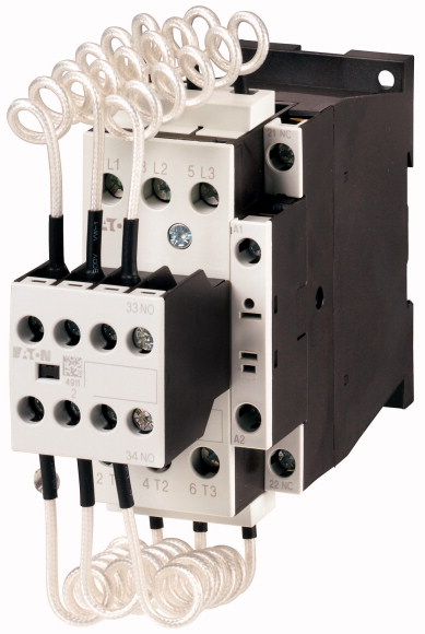
Contactor for capacitors, with series resistors, 12.5 kVAr, 415 V 50 Hz, 480 V 60 HzFor switching in central compensation systems with 180-fold transient peaks. The capacitors are pre-charged via the early-make auxiliary contacts and the fitted wire resistors, thus reducing the inrush current.
Contactor for capacitors, with series resistors, 12.5 kVAr, 415 V 50 Hz, 480 V 60 Hz
For switching in central compensation systems with 180-fold transient peaks. The capacitors are pre-charged via the early-make auxiliary contacts and the fitted wire resistors, thus reducing the inrush current.
| Product range | DILK Contactors for capacitors |
| Application | Contactors for power factor correction |
| Description | with series resistors |
| Open >230 V [Q] |
|
| Open >400 V [Q] |
7.5 kVAr |
| Open >525 V [Q] |
12.5 kVAr |
| Open >690 V [Q] |
16.7 kVAr |
| Contact sequence | 20 kVAr |
| Actuating voltage | |
| Instructions | 415 V 50 Hz, 480 V 60 Hz |
| Standards | In the case of group compensation multi-stage capacitor banks are connected to the mains, as required. Transient currents of up to 180 × Ie could flow between the capacitors. The capacitors are pre-charged via the early-make auxiliary contacts and the fitted wire resistors, thereby reducing the inrush current. The main contacts then close in a time-delayed manner and bring about the continuous current. Due to their special contacts, the contactors for the capacitors are weld-resistant for capacitors with inrush current peaks Due to their special contacts, the contactors for capacitors are weld-resistant for capacitors with inrush current peaks up to 180 × le. |
| Ambient temperature >Open |
|
| Ambient temperature >Enclosed |
IEC/EN 60947 |
| Mounting position | -25 - +60 °C |
| Degree of Protection | - 25 - 40 °C |
| Protection against direct contact when actuated from front (EN 50274) | |
| Altitude | IP00 |
| Weight basic unit >AC operated |
Finger and back-of-hand proof |
| Terminal capacity main cable >Solid |
Max. 2000 m |
| Terminal capacity main cable >Flexible with ferrule |
0.51 kg |
| Terminal capacity main cable >Stranded |
1 x (0.75 - 16) mm2 |
| Terminal capacity main cable >Solid or stranded |
1 x (0.75 - 16) mm2 |
| Terminal capacity main cable >Flat conductor [Lamellenzahl x Breite x Dicke ] |
1 x 16 mm2 |
| Rated power of AC-6b three-phase capacitors, 50 - 60 Hz >Open >230 V [Q] |
18 - 6 AWG |
| Rated power of AC-6b three-phase capacitors, 50 - 60 Hz >Open >400 V [Q] |
- mm |
| Rated power of AC-6b three-phase capacitors, 50 - 60 Hz >Open >525 V [Q] |
7.5 kVAr |
| Rated power of AC-6b three-phase capacitors, 50 - 60 Hz >Open >690 V [Q] |
12.5 kVAr |
| Rated operational current Ie of three-phase capacitors >Open >230 V [Ie] |
16.7 kVAr |
| Rated operational current Ie of three-phase capacitors >Open >400 V [Ie] |
20 kVAr |
| Rated operational current Ie of three-phase capacitors >Open >525 V [Ie] |
18 A |
| Rated operational current Ie of three-phase capacitors >Open >690 V [Ie] |
18 A |
| Rated operational current Ie of three-phase capacitors >of three-phase capacitors enclosed [Ie ] >230 V [Ie] |
18 A |
| Rated operational current Ie of three-phase capacitors >of three-phase capacitors enclosed [Ie ] >400 V [Ie] |
18 A |
| Rated operational current Ie of three-phase capacitors >of three-phase capacitors enclosed [Ie ] >525 V [Ie] |
16 A |
| Rated operational current Ie of three-phase capacitors >of three-phase capacitors enclosed [Ie ] >690 V [Ie] |
16 A |
| Making capacity (i-peak value) without damping | 16 A |
| Component lifespan [Operations] | 16 A |
| Maximum operating frequency >Max. operating frequency |
180 x Ie |
| Voltage tolerance >AC operated [Pick-up] |
0.15 x 10⁶ |
| Voltage tolerance >Drop-out voltage AC operated [Drop-out] |
120 Ops/h |
| Power consumption of the coil in a cold state and 1.0 x US >50 Hz [Pick-up] |
|
| Power consumption of the coil in a cold state and 1.0 x US >50 Hz [Sealing] |
0.8 - 1.1 x Uc |
| Power consumption of the coil in a cold state and 1.0 x US >50 Hz [Sealing] |
0.3 - 0.6 x Uc |
| Power consumption of the coil in a cold state and 1.0 x US >60 Hz [Pick-up] |
58 VA |
| Power consumption of the coil in a cold state and 1.0 x US >60 Hz [Sealing] |
7.6 VA |
| Power consumption of the coil in a cold state and 1.0 x US >60 Hz [Sealing] |
2.1 W |
| Duty factor | 71 VA |
| Changeover time at 100 % US (recommended value) >Main contacts >AC operated >Closing delay |
9.3 VA |
| Changeover time at 100 % US (recommended value) >Main contacts >AC operated >Opening delay |
2.1 W |
| Arcing time | 100 % DF |
| Emitted interference | 16 - 22 ms |
| Interference immunity | 8 - 14 ms |
| like the contactar [DIL] | 10 ms |
| Auxiliary contacts >Pilot Duty >AC operated |
|
| Auxiliary contacts >Pilot Duty >DC operated |
according to EN 60947-1 |
| Auxiliary contacts >General Use >AC |
according to EN 60947-1 |
| Auxiliary contacts >General Use >AC |
|
| Auxiliary contacts >General Use >DC |
M17 |
| Auxiliary contacts >General Use >DC |
|
| Special Purpose Ratings >Capacitor Switching >240V 60Hz 3phase |
A600 |
| Special Purpose Ratings >Capacitor Switching >240V 60Hz 3phase |
P300 |
| Special Purpose Ratings >Capacitor Switching >480V 60Hz 3phase |
600 V |
| Special Purpose Ratings >Capacitor Switching >480V 60Hz 3phase |
10 A |
| Special Purpose Ratings >Capacitor Switching >600V 60Hz 3phase |
250 V |
| Special Purpose Ratings >Capacitor Switching >600V 60Hz 3phase |
1 A |
| Rated operational current for specified heat dissipation [In] | 18 A |
| Heat dissipation per pole, current-dependent [Pvid] | 7.5 kVar |
| Equipment heat dissipation, current-dependent [Pvid] | 18 A |
| Static heat dissipation, non-current-dependent [Pvs] | 15 kVar |
| Heat dissipation capacity [Pdiss] | 14.4 A |
| Operating ambient temperature min. | 15 kVar |
| Operating ambient temperature max. | |
| 10.2 Strength of materials and parts >10.2.2 Corrosion resistance |
18 A |
| 10.2 Strength of materials and parts >10.2.3.1 Verification of thermal stability of enclosures |
0.7 W |
| 10.2 Strength of materials and parts >10.2.3.2 Verification of resistance of insulating materials to normal heat |
2.1 W |
| 10.2 Strength of materials and parts >10.2.3.3 Verification of resistance of insulating materials to abnormal heat and fire due to internal electric effects |
2.1 W |
| 10.2 Strength of materials and parts >10.2.4 Resistance to ultra-violet (UV) radiation |
0 W |
| 10.2 Strength of materials and parts >10.2.5 Lifting |
-25 °C |
| 10.2 Strength of materials and parts >10.2.6 Mechanical impact |
+60 °C |
| 10.2 Strength of materials and parts >10.2.7 Inscriptions |
|
| 10.3 Degree of protection of ASSEMBLIES | Meets the product standard´s requirements. |
| 10.4 Clearances and creepage distances | Meets the product standard´s requirements. |
| 10.5 Protection against electric shock | Meets the product standard´s requirements. |
| 10.6 Incorporation of switching devices and components | Meets the product standard´s requirements. |
| 10.7 Internal electrical circuits and connections | Meets the product standard´s requirements. |
| 10.8 Connections for external conductors | Does not apply, since the entire switchgear needs to be evaluated. |
| 10.9 Insulation properties >10.9.2 Power-frequency electric strength |
Does not apply, since the entire switchgear needs to be evaluated. |
| 10.9 Insulation properties >10.9.3 Impulse withstand voltage |
Meets the product standard´s requirements. |
| 10.9 Insulation properties >10.9.4 Testing of enclosures made of insulating material |
Does not apply, since the entire switchgear needs to be evaluated. |
| 10.10 Temperature rise | Meets the product standard´s requirements. |
| 10.11 Short-circuit rating | Does not apply, since the entire switchgear needs to be evaluated. |
| 10.12 Electromagnetic compatibility | Does not apply, since the entire switchgear needs to be evaluated. |
| 10.13 Mechanical function | Is the panel builder´s responsibility. |
| Rated control supply voltage Us at AC 50HZ | Is the panel builder´s responsibility. |
| Rated control supply voltage Us at AC 60HZ | Is the panel builder´s responsibility. |
| Rated control supply voltage Us at DC | Is the panel builder´s responsibility. |
| Voltage type for actuating | Is the panel builder´s responsibility. |
| Number of auxiliary contacts as normally open contact | The panel builder is responsible for the temperature rise calculation. Eaton will provide heat dissipation data for the devices. |
| Number of auxiliary contacts as normally closed contact | Is the panel builder´s responsibility. The specifications for the switchgear must be observed. |
| Type of electrical connection of main circuit | Is the panel builder´s responsibility. The specifications for the switchgear must be observed. |
| Number of main contacts as normally open contact | The device meets the requirements, provided the information in the instruction leaflet (IL) is observed. |
| Number of normally closed contacts as main contact | |
| Rated blind power at 400 V, 50 Hz | |
| Product Standards | 415 - 415 V |
| UL File No. | 480 - 480 V |
| UL Category Control No. | 0 - 0 V |
| CSA File No. | AC |
| CSA Class No. | 1 |
| North America Certification | 1 |
| Specially designed for North America | Screw connection |
All of our products ensure maximum reliability even in challenging working conditions and help your business operations run smoothly. The products we offer in industrial automation, energy management, cabling solutions, and many other areas adapt flexibly to the needs of different sectors.
Additionally, our products are manufactured using only high-quality materials and comply with international standards. Through the solutions we provide, we enable our customers to increase operational efficiency and optimize costs. Our company closely follows technological advancements and continuously offers innovative products to help our customers gain a competitive advantage.
On each of our product pages, you can find comprehensive information about technical details, areas of use, and product features. You can explore all the products you need to strengthen your industrial processes on our website and enjoy a seamless purchasing experience.
Similar Products


Can't find the product you're looking for?
LET US HELP YOU
Can't Find the Product You're Looking For? Let Us Know, and We'll Source It for You!
Are you searching for products not listed on our website or out of stock? Let us know your requirements, and our expert team will contact you as soon as possible to find the most suitable solution for you.