Eaton : 22DDILE
049823 22DDILE
22DDILE /49823
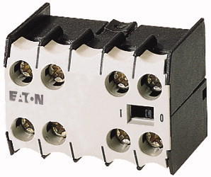
Auxiliary contact module, 4 pole, 1 N/O, 1 N/OE, 1 NC, 1 NCL, Front fixing, Screw terminals, DILE(E)M, DILERAuxiliary contact module, Function: for standard applications, 4 pole, Connection technique: Screw terminals, Rated operational current AC-15 220 V 230 V 240 V: Ie= 4 A, Rated operational current AC-15 380 V 400 V 415 V: Ie= 2 A, Contacts N/O = Normally open: 1 N/O, Contacts N/OE: NO early-make: 1 N/OE, Contacts N/C = Normally closed: 1 NC, Contacts NCL=NC late-break: 1 NCL, Mounting type: Front fixing, For use with: DILEM-10(-G)(…), DILEM-01(-G)(…), DILEM-4(-G)(…), DILER40(-G), DILER31(-G), DILER22, DILEEM-10(-G)(…), DILEEM-01(-G)(…), DILEM12-10(-G)(…), DILEM12-01(-G)(…), Instructions: Auxiliary contacts used as mirror contacts according to IEC/EN 60947-4-1 Appendix F (not N/C late open), Code number and version of combination Distinctive number: 62, 53, 44
Auxiliary contact module, 4 pole, 1 N/O, 1 N/OE, 1 NC, 1 NCL, Front fixing, Screw terminals, DILE(E)M, DILER
Auxiliary contact module, Function: for standard applications, 4 pole, Connection technique: Screw terminals, Rated operational current AC-15 220 V 230 V 240 V: Ie= 4 A, Rated operational current AC-15 380 V 400 V 415 V: Ie= 2 A, Contacts N/O = Normally open: 1 N/O, Contacts N/OE: NO early-make: 1 N/OE, Contacts N/C = Normally closed: 1 NC, Contacts NCL=NC late-break: 1 NCL, Mounting type: Front fixing, For use with: DILEM-10(-G)(…), DILEM-01(-G)(…), DILEM-4(-G)(…), DILER40(-G), DILER31(-G), DILER22, DILEEM-10(-G)(…), DILEEM-01(-G)(…), DILEM12-10(-G)(…), DILEM12-01(-G)(…), Instructions: Auxiliary contacts used as mirror contacts according to IEC/EN 60947-4-1 Appendix F (not N/C late open), Code number and version of combination Distinctive number: 62, 53, 44
| Accessories | Auxiliary contact modules |
| Function | for standard applications |
| Number of poles | 4 pole |
| Connection technique | Screw terminals |
| AC-15 >220 V 230 V 240 V [Ie] |
|
| AC-15 >380 V 400 V 415 V [Ie] |
4 A |
| N/O = Normally open | 2 A |
| N/OE: NO early-make | |
| N/C = Normally closed | 1 N/O |
| NCL=NC late-break | 1 N/OE |
| Mounting type | 1 NC |
| Contact sequence | 1 NCL |
| For use with | Front fixing |
| Instructions | |
| Distinctive number | DILEM-10(-G)(…) DILEM-01(-G)(…) DILEM-4(-G)(…) DILER40(-G) DILER31(-G) DILER22 DILEEM-10(-G)(…) DILEEM-01(-G)(…) DILEM12-10(-G)(…) DILEM12-01(-G)(…) |
| with basic device | Auxiliary contacts used as mirror contacts according to IEC/EN 60947-4-1 Appendix F (not N/C late open) |
| with basic device | |
| with basic device | 62 |
| Standards | DILER-40(-G) |
| Lifespan, mechanical >AC operated [Operations] |
53 |
| Lifespan, mechanical >DC operated [Operations] |
DILER-31(-G) |
| Component lifespan at Ue = 240 V >AC-15 [Operations] |
44 |
| Component lifespan at Ue = 240 V >DC >L/R = 50 ms: 2 contacts in series at Ie = 0.5 A [Operations] |
DILER-22 |
| Maximum operating frequency [Operations/h] | |
| Climatic proofing | IEC/EN 60947, VDE 0660, UL, CSA |
| Ambient temperature >Open |
10 x 106 |
| Ambient temperature >Enclosed |
20 x 106 |
| Ambient temperature >Ambient temperature, storage |
0.2 x 10⁶ |
| Mounting position >Mounting position |
0.15 x 10⁶ |
| Mechanical shock resistance (IEC/EN 60068-2-27) >Half-sinusoidal shock, 10 ms >Basic unit with auxiliary contact module >N/O contact |
9000 |
| Mechanical shock resistance (IEC/EN 60068-2-27) >Half-sinusoidal shock, 10 ms >Basic unit with auxiliary contact module >N/C contact |
Damp heat, constant, to IEC 60068-2-78 Damp heat, cyclic, to IEC 60068-2-30 |
| Degree of Protection | -25 - +50 °C |
| Protection against direct contact when actuated from front (EN 50274) | - 25 - 40 °C |
| Weight | - 40 - 80 °C |
| Terminal capacities >Screw terminals >Solid |
As required, except vertical with terminals A1/A2 at the bottom |
| Terminal capacities >Screw terminals >Flexible with ferrule |
10 g |
| Terminal capacities >Screw terminals >Solid or stranded |
8 g |
| Terminal capacities >Screw terminals >Terminal screw |
IP20 |
| Terminal capacities >Screw terminals >Pozidriv screwdriver |
Finger and back-of-hand proof |
| Terminal capacities >Screw terminals >Standard screwdriver |
0.04 kg |
| Terminal capacities >Screw terminals >Max. tightening torque |
1 x (0.75 - 2.5) 2 x (0.75 - 2.5) mm2 |
| Interlocked opposing contacts within an auxiliary contact module (to IEC 60947-5-1 Annex L) | 1 x (0.75 - 1.5) 2 x (0.75 - 1.5) mm2 |
| Rated impulse withstand voltage [Uimp] | Single 18 – 14/Double 18 – 14 AWG |
| Overvoltage category/pollution degree | M3.5 |
| Rated insulation voltage [Ui] | 2 Size |
| Rated operational voltage [Ue] | 0.8 x 5.5 1 x 6 mm |
| Safe isolation to EN 61140 >between coil and auxiliary contacts |
1.2 Nm |
| Safe isolation to EN 61140 >between the auxiliary contacts |
|
| Rated operational current >Conventional free air thermal current, 1 pole >Notes |
No |
| Rated operational current >Conventional free air thermal current, 1 pole >Conv. thermal current [Ith] |
6000 V AC |
| Rated operational current >AC-15 >220 V 230 V 240 V [Ie] |
III/3 |
| Rated operational current >AC-15 >380 V 400 V 415 V [Ie] |
690 V AC |
| Rated operational current >AC-15 >500 V [Ie] |
600 V AC |
| Rated operational current >DC current |
300 V AC |
| Rated operational current >DC current >DC L/R ≦ 15 ms >Contacts in series: >1 [24 V] |
300 V AC |
| Rated operational current >DC current >DC L/R ≦ 15 ms >Contacts in series: >2 [60 V] |
At maximum permissible ambient air temperature. |
| Rated operational current >DC current >DC L/R ≦ 15 ms >Contacts in series: >3 [110 V] |
10 A |
| Rated operational current >DC current >DC L/R ≦ 15 ms >Contacts in series: >3 [220 V] |
4 A |
| Rated operational current >Control circuit reliability [Failure rate] |
2 A |
| Short-circuit rating without welding >Maximum overcurrent protective device >220 V 230 V 240 V |
1.5 A |
| Short-circuit rating without welding >Maximum overcurrent protective device >380 V 400 V 415 V |
Switch-on and switch-off conditions based on DC-13, time constant as specified. |
| Short-circuit rating without welding >Short-circuit protection maximum fuse >500 V |
2.5 A |
| Short-circuit rating without welding >Short-circuit protection maximum fuse >500 V |
2.5 A |
| Current heat loss at Ith >AC operated |
1.5 A |
| Current heat loss at Ith >DC operated |
0.5 A |
| Current heat loss at Ith >Current heat loss per auxiliary circuit at Ie (AC-15/230 V) |
<10-8, < one failure at 100 million operations (at Ue = 24 V DC, Umin = 17 V, Imin = 5.4 mA) λ |
| Auxiliary contacts >Pilot Duty >AC operated |
4 PKZM0 |
| Auxiliary contacts >Pilot Duty >DC operated |
4 PKZM0 |
| Auxiliary contacts >General Use >AC |
6 A gG/gL |
| Auxiliary contacts >General Use >AC |
10 A fast |
| Auxiliary contacts >General Use >DC |
1.5 W |
| Auxiliary contacts >General Use >DC |
1.5 W |
| Rated operational current for specified heat dissipation [In] | 0.24 CO |
| Heat dissipation per pole, current-dependent [Pvid] | |
| Equipment heat dissipation, current-dependent [Pvid] | A600 |
| Static heat dissipation, non-current-dependent [Pvs] | P300 |
| Heat dissipation capacity [Pdiss] | 600 V |
| Operating ambient temperature min. | 10 A |
| Operating ambient temperature max. | 250 V |
| 10.2 Strength of materials and parts >10.2.2 Corrosion resistance |
0.5 A |
| 10.2 Strength of materials and parts >10.2.3.1 Verification of thermal stability of enclosures |
|
| 10.2 Strength of materials and parts >10.2.3.2 Verification of resistance of insulating materials to normal heat |
4 A |
| 10.2 Strength of materials and parts >10.2.3.3 Verification of resistance of insulating materials to abnormal heat and fire due to internal electric effects |
0.24 W |
| 10.2 Strength of materials and parts >10.2.4 Resistance to ultra-violet (UV) radiation |
0 W |
| 10.2 Strength of materials and parts >10.2.5 Lifting |
0 W |
| 10.2 Strength of materials and parts >10.2.6 Mechanical impact |
0 W |
| 10.2 Strength of materials and parts >10.2.7 Inscriptions |
-25 °C |
| 10.3 Degree of protection of ASSEMBLIES | +50 °C |
| 10.4 Clearances and creepage distances | |
| 10.5 Protection against electric shock | Meets the product standard´s requirements. |
| 10.6 Incorporation of switching devices and components | Meets the product standard´s requirements. |
| 10.7 Internal electrical circuits and connections | Meets the product standard´s requirements. |
| 10.8 Connections for external conductors | Meets the product standard´s requirements. |
| 10.9 Insulation properties >10.9.2 Power-frequency electric strength |
Meets the product standard´s requirements. |
| 10.9 Insulation properties >10.9.3 Impulse withstand voltage |
Does not apply, since the entire switchgear needs to be evaluated. |
| 10.9 Insulation properties >10.9.4 Testing of enclosures made of insulating material |
Does not apply, since the entire switchgear needs to be evaluated. |
| 10.10 Temperature rise | Meets the product standard´s requirements. |
| 10.11 Short-circuit rating | Does not apply, since the entire switchgear needs to be evaluated. |
| 10.12 Electromagnetic compatibility | Meets the product standard´s requirements. |
| 10.13 Mechanical function | Does not apply, since the entire switchgear needs to be evaluated. |
| Number of contacts as change-over contact | Does not apply, since the entire switchgear needs to be evaluated. |
| Number of contacts as normally open contact | Is the panel builder´s responsibility. |
| Number of contacts as normally closed contact | Is the panel builder´s responsibility. |
| Number of fault-signal switches | Is the panel builder´s responsibility. |
| Rated operation current Ie at AC-15, 230 V | Is the panel builder´s responsibility. |
| Type of electric connection | Is the panel builder´s responsibility. |
| Model | The panel builder is responsible for the temperature rise calculation. Eaton will provide heat dissipation data for the devices. |
| Mounting method | Is the panel builder´s responsibility. The specifications for the switchgear must be observed. |
| Lamp holder | Is the panel builder´s responsibility. The specifications for the switchgear must be observed. |
| Product Standards | The device meets the requirements, provided the information in the instruction leaflet (IL) is observed. |
| UL File No. | |
| UL Category Control No. | |
| CSA File No. | 0 |
| CSA Class No. | 2 |
| North America Certification | 2 |
| Specially designed for North America | 0 |
| Characteristic curve | 4 A |
| Characteristic curve | Screw connection |
| Characteristic curve | Top mounting |
All of our products ensure maximum reliability even in challenging working conditions and help your business operations run smoothly. The products we offer in industrial automation, energy management, cabling solutions, and many other areas adapt flexibly to the needs of different sectors.
Additionally, our products are manufactured using only high-quality materials and comply with international standards. Through the solutions we provide, we enable our customers to increase operational efficiency and optimize costs. Our company closely follows technological advancements and continuously offers innovative products to help our customers gain a competitive advantage.
On each of our product pages, you can find comprehensive information about technical details, areas of use, and product features. You can explore all the products you need to strengthen your industrial processes on our website and enjoy a seamless purchasing experience.
Similar Products


Can't find the product you're looking for?
LET US HELP YOU
Can't Find the Product You're Looking For? Let Us Know, and We'll Source It for You!
Are you searching for products not listed on our website or out of stock? Let us know your requirements, and our expert team will contact you as soon as possible to find the most suitable solution for you.